
6CProto Engineering Guides
Injection Molding Assembly & Process Control Guides
Engineering references for snap fits, inserts & overmolding design.
Updated November 2026 · 31 articles
Assembly is designed, not discovered
Most molded assemblies are held together by features that were drawn in minutes and never analysed: a snap arm, a press-fit boss, a heat stake. Each has a working range, and the range is narrower than it looks. A snap arm depends on the strain at its root staying below the material’s allowable deflection, which depends on the grade, the temperature and the speed of assembly. A boss depends on the hoop stress the insert puts into the plastic, which depends on the boss wall and the interference.
The design rule that follows is to give every joint a defined load path. If a snap carries the panel, the panel should not also rest on the snap; if an insert takes the screw load, the boss should sit on a rib rather than hang in the air.
Overmolding and multi-shot parts
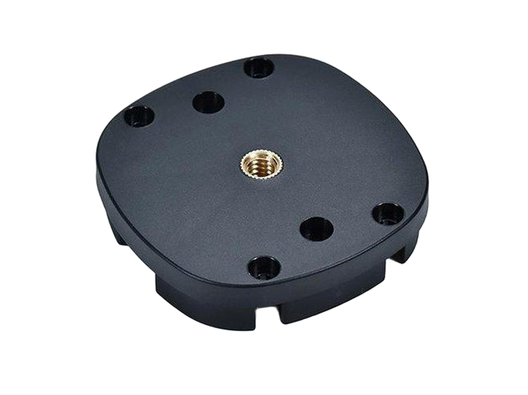
An overmolded grip needs two things beyond adhesion: a mechanical interlock, because chemical bonding between dissimilar resins is unreliable, and a substrate that can survive the second shot’s melt temperature and injection pressure. Designing the substrate with through-holes, ribs or a dovetail edge is cheaper than adding a primer or changing the resin pair.
The same logic applies to insert molding. A metal insert that is loaded in tension should have a knurl or a shoulder rather than relying on shrinkage alone, and the surrounding wall should be thick enough to resist the insertion force without cracking at the gate.
Where the joint fails in service
Three failure modes dominate. Creep: a snap that holds on day one relaxes under sustained load and releases in month three. Weld lines: a hinge or clip placed opposite the gate sits on the weakest line in the part. Tolerance stack: a clip that engages by 0.8 mm nominal loses its engagement when two parts stack at their extremes. All three are design problems with drawing-level fixes, and all three are cheaper to solve before the tool is cut.
Welded joints follow the same logic. Ultrasonic welding needs a designed energy director and a joint line that can hold the horn; a joint that is merely pressed together will weld unevenly and fail at the first drop. Heat staking needs a boss with the right wall and a stud long enough to form a head, and the stake appearance is a cosmetic decision as much as a structural one.
The common thread is that the assembly feature is a molded feature. It has draft, wall thickness and a gate relationship of its own, and it is inspected like any other dimension on the part.
Find the guide for your next decision
Follow the guide that matches the feature, failure mode or project decision you are working on.
Prototype Insert Molding: Getting a Representative Part Before the Tool Is Committed
Overmolding vs Insert Molding: A Process Selection Guide
TPU Overmold Hardness Selection for Grips and Seals
Insert Molding Design for Manufacturability: Locating Metal Before the Shot
Overmolding Services: When a Second Shot Is Worth the Tooling Complexity
Cantilever Snap Fit Calculation: From Assembly Deflection to Root Strain
Injection Molded Snap Fit Weld Lines: Keep the Flow Front Away From the Flexing Root
Snap Fit Fatigue: Designing Latches for Repeated Opening Cycles
Overmolding Insert Movement: Locating the Substrate Before the Second Shot
Snap Fit vs Screws: Assembly Time, Service Access and Tooling Complexity
Snap Fit Creep: Preventing Retention Loss Under Sustained Deflection
Injection Molding Snap Fit Design: Tool Access, Release and Repeated Assembly
U Shaped Snap Fit Design: Packaging Flexibility Into a Short Assembly
Annular Snap Joint Design: Interference, Hoop Strain and Mold Release
Liquid Silicone Rubber (LSR) Molding: Process Window Buyers Should Ask About
Injection Molding Cost & Quotes: A Low-Volume Budgeting Guide
Mold Mismatch Troubleshooting: Separating Tool Alignment From Part Distortion
Prototype Mold Engineering Changes: When to Cut Steel and When to Replace an Insert
ABS Injection Molding Moisture: Drying Evidence and Splay Troubleshooting
Cooling Uniformity for Translucent Thin-Wall Mouldings
Measuring Wall Thickness on Thin Moulded Lighting Parts
Change Control and Mold Maintenance Traceability for Medical Tooling
Cleanliness and Packaging Requirements for Medical Molded Parts
Medical-Grade Plastic Selection for Injection Molded Device Parts
Medical Mold Qualification: What IQ, OQ and PQ Actually Require
Injection Mold Transfer Checklist: Verify the Tool Before Quoting Production at a New Shop
Quick Turn Injection Molding Design Freeze: Which Decisions Must Precede the Tool Cut
Soft Tooling Accuracy: Separate Fixture Movement From Part Shrinkage in a Pilot Batch
Injection Molding Ejector Pin Marks: Placement, Support and Cosmetic Acceptance
Injection Molding Gate Blush: Separate Flow Marks From Surface Damage
Injection Molding Gate Vestige: Specify the Residual Feature Before Tool Design
Before you release the project
- Define the function, environment and the question this batch must answer.
- Specify material grade, geometry, quantity, finish and the dimensions that control fit.
- Agree the inspection method and the evidence required to accept the parts.
- Record the drawing revision and approval before production begins.
Common planning questions
When should I commit to production tooling?
After the design, molding grade, expected quantity and validation plan are sufficiently settled. A prototype mold can reduce uncertainty, but its behavior is not automatically identical to the final production tool.
Can simulation guarantee a defect-free molded part?
No. Simulation helps identify risks using the supplied assumptions. Tool trials, process control and inspection are still needed to validate the actual part.
Move from guidance to a reviewed project
Send the CAD model and drawing with material, quantity, finish and inspection requirements. Use the relevant service page to review the available manufacturing route.