

A pilot batch can show a changing hole spacing even when the cavity drawing has not changed. The movement may come from the tool, the part’s cooling history, a restraining fixture, or the way the measurement is taken. Cutting a compensation into the next tool before separating those effects can preserve the wrong correction.
Soft tooling accuracy is therefore a system question. Identify the tooling material and process first, then distinguish tool geometry, free-state part geometry, and constrained assembly geometry. A compliant silicone mold, an aluminum injection mold, and a temporary locating nest have different behaviors even when all are casually called soft tooling.
The decision is not whether a pilot part looks accurate enough. It is which observed dimensions are valid evidence for a production-tool decision, and under which material, temperature, support, and conditioning conditions that evidence applies. Treat repeatability within one setup separately from transferability to another manufacturing route.
For process selection context, the rapid-prototyping service covers several fabrication routes. The dimensional investigation below concerns the evidence needed to interpret a pilot batch without assigning every deviation to material shrinkage.
What determines soft tooling accuracy in a pilot batch?
Tool behavior and measurement conditions both matter.
Identify the mold material, forming process, part condition and restraint, then compare tool references with free-state parts before treating a dimensional difference as a shrinkage correction alone.
Start by naming the actual route. A cast elastomer tool may deform under handling or closure; a machined metal mold has a different stiffness and thermal response. The tooling label cannot substitute for a description of support, closure, inserts, and the sequence used to produce the part.
For injection molding, Autodesk’s warpage explanation identifies differential shrinkage, cooling, and orientation as distinct contributors. That makes a single average shrinkage factor a poor explanation for a part whose local shape and orientation are changing.
Record tool identifiers and the locations used to check the tool itself. A dimensional result on the finished part cannot reveal whether the cavity or a removable insert moved unless another observation isolates that possibility. Preserve the as-built tool record before modifying it in response to the first trial.
Separate fixture movement from part shrinkage
Measure the part in at least the conditions required to answer the investigation: the defined free state and the relevant constrained state. Keep support points and clamping consistent within each condition. If the part changes shape when released, the fixture is participating in the result rather than merely holding it.
Check fixture references independently. A pilot nest can shift because of loose locating elements, thermal effects, wear, or an assembly change. Repeating the same measurement in a moving nest can produce a stable-looking number while the relationship to the part’s functional datum changes.
NIST’s measurement-process framework treats calibration, control, repeatability, and uncertainty as different parts of measurement characterization. Use that separation to plan observations, not to assume a particular instrument automatically resolves the problem.
For a bowed strip, compare length and profile without forcing it flat, then repeat under a documented assembly constraint. Report these as different measurands. Calling both “length” without defining restraint can create a disagreement that no additional decimal place will solve.
Document the validation boundary
A pilot tool can validate access, assembly, local geometry, or an early material choice without representing every aspect of a production tool. Write down which questions the batch was intended to answer before interpreting its results. Otherwise, an encouraging fit check can expand into an unsupported process-capability claim.
List differences from the proposed production route: tool material, cavity count, gating, cooling, ejection, resin grade, and any secondary fixture. Explain which differences may affect the characteristics under review. Autodesk’s injection-location design guidance shows why gating belongs in this comparison: flow and packing are connected to part behavior.
If a part requires a restraining fixture after demolding, identify that fixture as a controlled process input. Do not present the restrained geometry as the natural free-state result. The production plan must either preserve that step or establish another way to meet the requirement.
Use the prototype injection-molding scope to frame the trial separately from production approval. State the decision being supported and the evidence still needed after the pilot.
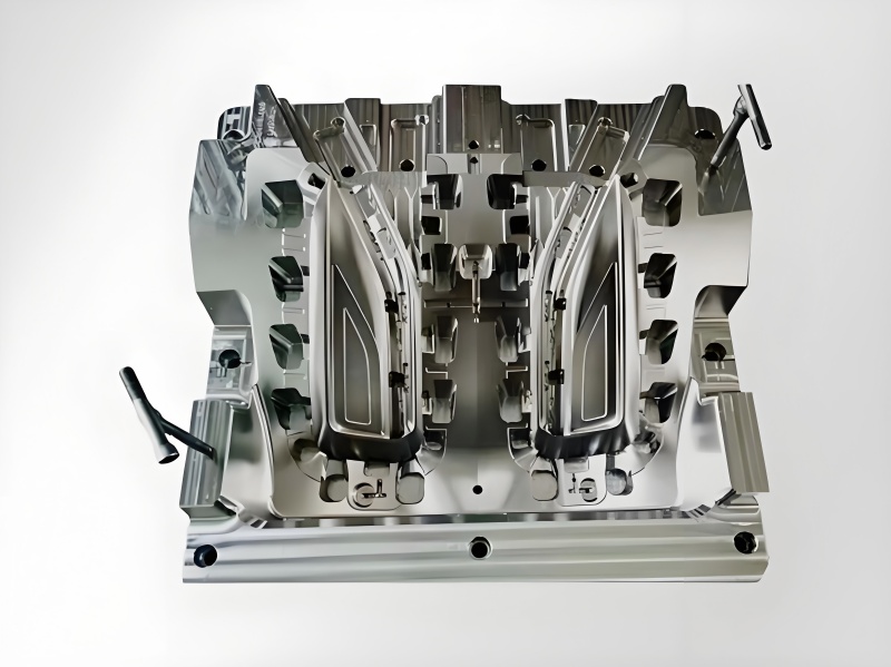
Choose evidence for the production tool decision
Choose evidence that discriminates between possible causes. If insert movement is suspected, measure insert references before and after the run. If conditioning is suspected, track identified parts over a defined interval. If measurement restraint is suspected, compare controlled support arrangements without changing the part population at the same time.
Avoid changing several variables in one corrective trial unless the purpose is a combined process demonstration. A successful combined change may produce acceptable parts but leave the root cause unresolved. That is a weak basis for predicting what will happen after another tool or fixture change.
Autodesk’s sink-mark and void discussion describes localized cooling shrinkage and packing effects. It supports inspecting the geometry and integrity associated with a local thick section instead of assuming every surface depression is a global cavity-size error.
For the production-tool review, present paired evidence: tool condition, part condition, measurement setup, and the resulting characteristic. Include failed or unstable conditions when they define the usable process boundary. A selected photograph of the best pilot part is not a dimensional investigation.
Decision-gate and evidence matrix
The production-tool decision should distinguish a geometry correction from a process or measurement correction. These actions have different consequences and should not be approved from the same unexplained dimensional average. Use the matrix to assign the next investigation to the suspected contributor.
The observations below are diagnostic directions. They are not proof of a cause until the investigation controls relevant alternatives and demonstrates that the measurement method can resolve the effect.
| Observation | Possible contributor | Discriminating check | Release implication |
|---|---|---|---|
| Tool references shift during trial | Insert or support movement | Check tool references independently | Stabilize tool before compensation |
| Free part differs from restrained part | Fixture-induced shape | Defined support comparison | Specify accepted state |
| Identified parts change after cooling | Time or conditioning effect | Timed repeated measurements | Define measurement condition |
| Different operators disagree | Setup or measurement variation | Reclamp and operator study | Resolve method first |
The NIST uncertainty framework provides a basis for evaluating whether the apparent difference is meaningful relative to measurement quality. Do not cut a permanent tool correction to chase a shift the current setup cannot distinguish reliably.
Worked pilot-batch investigation example
Assume an illustrative pilot bracket has two holes nominally 100.00 mm apart. The measured spacing is 99.70 mm in a flat inspection nest and 99.85 mm under a defined low-restraint support. The cavity reference remains unchanged within the investigation’s demonstrated measurement capability. These are assumed readings, not production results or supplier tolerances.
The difference between the two part measurements is 0.15 mm. It cannot automatically be assigned to shrinkage because the support condition changed. The immediate task is to determine which condition matches the drawing’s acceptance state and whether the nest is deforming the bracket.
Next measure identified parts at the agreed condition and time, then repeat the setup after complete removal and replacement. Retain profile data if bowing changes the projected hole spacing. A one-dimensional correction factor would discard that shape information.
Only after this separation should the team consider cavity compensation. The low-volume manufacturing transition should carry the accepted support and conditioning requirements forward, rather than treating a pilot tool’s compensation as a process-independent material constant.
Acceptance records and limits of the prototype evidence
Preserve the raw dimensional results with part identity, measurement time, temperature or conditioning description, fixture version, and tool condition. Summaries are useful, but they should remain traceable to the observations that support them. A batch average cannot explain whether every part drifted or one cavity behaved differently.
NIST’s account of short-term and time-dependent variability supports separating repeated readings from changes across a longer interval. A low spread during one inspection session does not establish stability through an entire pilot run or after storage.
Identify the accepted state explicitly: free, supported, or assembled under a defined constraint. If the drawing is ambiguous, resolve that ambiguity before labeling parts conforming. Recording the clamp torque alone may not define the resulting contact or deformation.
Keep the conclusions narrow. Pilot evidence can support a tooling decision under the investigated conditions, but it does not establish the long-run life of a soft mold, every production cavity’s behavior, or the equivalence of a different material grade. Those questions need additional evidence tied to their own requirements.
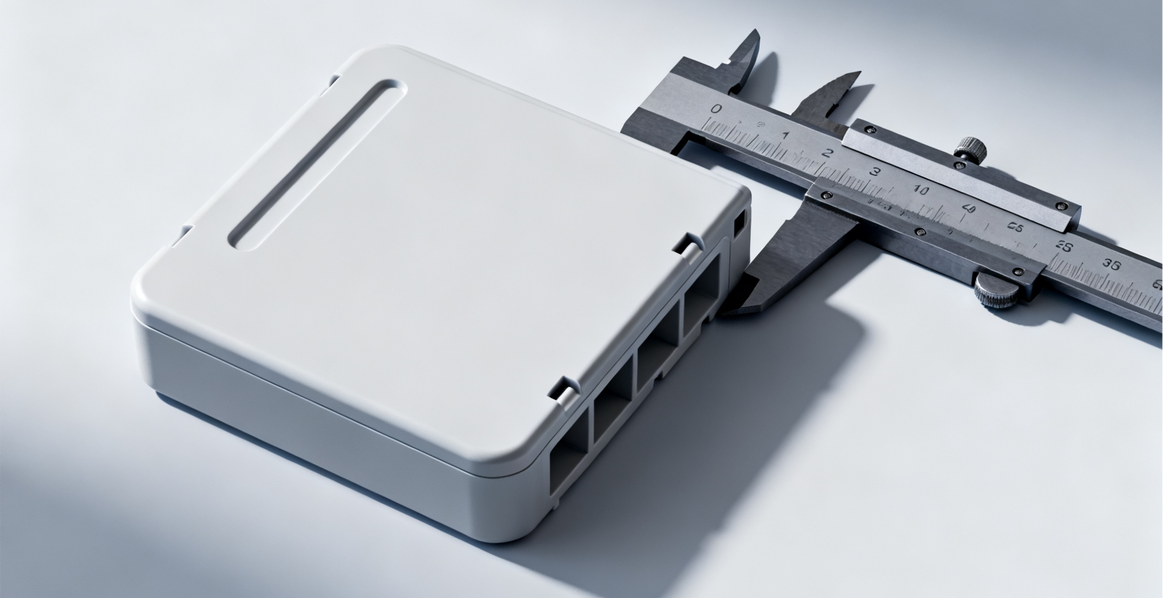
Release and handover checklist for the next build
The next toolmaker needs more than a corrected CAD file. Supply the investigation’s accepted measurement state, material identity, relevant part conditioning, tool references, and the rationale for any cavity change. Distinguish measured offsets from proposed compensations so a temporary pilot adjustment does not become an unexplained production dimension.
Preserve the tool and fixture versions used to generate the approved evidence. Include the locations of replaceable inserts and any supports that influence closure or part release. If the production process removes a restraining step, define the trial needed to demonstrate the alternative.
The Eastman molding troubleshooting document is useful for distinguishing defect mechanisms, but it cannot supply a universal compensation for an unspecified resin and geometry. The material supplier’s grade-specific information and actual trial observations must be evaluated together.
At handover, identify unresolved risks and their owners without mixing them into accepted data. The release should state which geometry is authorized, which process inputs remain controlled, and which measurements must be repeated at the production-tool trial before routine parts are approved.
FAQ
Can a soft-tooling trial establish production process capability?
A pilot trial can provide useful data, but capability conclusions require an appropriate measurement system and evidence that represents the intended production process and its variation. Tool material, cavity count, cooling, ejection, and handling may change during transfer. State what population and conditions the pilot data describe. If the trial was designed only to compare fit or investigate a dimensional mechanism, do not relabel it as a long-run capability study after acceptable samples appear.
Should a bowed pilot part be clamped flat for inspection?
Only when the drawing or agreed measurement definition requires that constraint, with its method documented. If free-state geometry controls acceptance, flattening the part can conceal the condition being evaluated. It can also change projected feature locations and create an apparent size shift. For assembly-restrained parts, record both the relevant functional check and the restraint used. Resolve an ambiguous acceptance state with the design authority before comparing suppliers or authorizing a permanent tooling correction.
Is one shrinkage percentage enough for a complex pilot part?
Usually it is insufficient as the complete explanation of dimensional behavior. Different sections, flow directions, constraints, and cooling conditions can produce different local changes. A global factor may be a preliminary modeling input, but the final tooling decision should consider critical feature relationships and shape. Retain the material grade and process assumptions behind any factor, and compare them with actual trial measurements. Avoid using one observed overall dimension to predict every local interface.
Conclusion
Soft-tooling results become useful when each number has a defined physical meaning. Separate tool movement, part movement, and measurement restraint before converting a pilot deviation into a permanent cavity correction. Preserve shape and condition information where a single size value would hide the mechanism.
The production-tool decision should follow evidence that distinguishes causes and represents the required acceptance state. A good pilot part is encouraging, but its value lies in the specific questions it answers. Keep the trial’s material, support, conditioning, and process limits visible in the handover package so the next build does not inherit a false assumption about shrinkage.
6CProto supports prototype and subsequent manufacturing routes, with DFM review to discuss the transition. To investigate a pilot geometry issue, send the part model, tool and fixture descriptions, raw measurements, and intended acceptance state for quotation. Include the decision the next trial must resolve before production tooling is released.
{“@context”: “https://schema.org”, “@type”: “FAQPage”, “mainEntity”: [{“@type”: “Question”, “name”: “Can a soft-tooling trial establish production process capability?”, “acceptedAnswer”: {“@type”: “Answer”, “text”: “A pilot trial can provide useful data, but capability conclusions require an appropriate measurement system and evidence that represents the intended production process and its variation. Tool material, cavity count, cooling, ejection, and handling may change during transfer. State what population and conditions the pilot data describe. If the trial was designed only to compare fit or investigate a dimensional mechanism, do not relabel it as a long-run capability study after acceptable samples appear.”}}, {“@type”: “Question”, “name”: “Should a bowed pilot part be clamped flat for inspection?”, “acceptedAnswer”: {“@type”: “Answer”, “text”: “Only when the drawing or agreed measurement definition requires that constraint, with its method documented. If free-state geometry controls acceptance, flattening the part can conceal the condition being evaluated. It can also change projected feature locations and create an apparent size shift. For assembly-restrained parts, record both the relevant functional check and the restraint used. Resolve an ambiguous acceptance state with the design authority before comparing suppliers or authorizing a permanent tooling correction.”}}, {“@type”: “Question”, “name”: “Is one shrinkage percentage enough for a complex pilot part?”, “acceptedAnswer”: {“@type”: “Answer”, “text”: “Usually it is insufficient as the complete explanation of dimensional behavior. Different sections, flow directions, constraints, and cooling conditions can produce different local changes. A global factor may be a preliminary modeling input, but the final tooling decision should consider critical feature relationships and shape. Retain the material grade and process assumptions behind any factor, and compare them with actual trial measurements. Avoid using one observed overall dimension to predict every local interface.”}}]}