

A short enclosure wall can leave too little straight-line space for a flexible latch. Folding the arm back into a U shaped snap fit creates a longer compliant path within that footprint, but the bend, adjoining wall and release opening become part of the spring. Simply bending a successful straight latch into a U does not preserve its force or strain distribution.
The design decision is therefore a packaging problem coupled to deformation. The hook must clear its mating ledge during insertion, return far enough to establish engagement and remain accessible when the assembly is serviced. A long flexible path offers little benefit if a rib stops it halfway through its required travel.
This guide concentrates on injection-molded U-shaped arms. Printed trial parts can establish access and assembly direction, while production material, molded geometry and conditioning are needed for a defensible repeated-release judgment. The overall enclosure and tool belong to the broader injection molding design review; the latch needs an additional examination of its moving envelope and its attachment to the wall. The aim is a joint that fits the available space without hiding a weak root or an impossible service action.
How does a U shaped snap fit gain travel in limited space?
The return path adds compliance within a short footprint.
Treat the two legs, connecting bend and supporting wall as one deforming system; assess hook travel, peak strain and interference under the intended assembly and release directions.
A U-shaped arm is a cantilever variation, as described in Covestro's snap-fit design guide. Its effective flexibility depends on the complete folded geometry. The free leg, bend and anchored leg do not behave like an isolated straight beam of equal overall width. A straight-beam calculation can help identify trends, but it should not be presented as a verified strain prediction for a compact U.
Trace the load from the hook into the enclosure. If the anchored leg joins a stiff wall, deformation may concentrate near that connection or the return bend. If the wall also flexes, the hook can travel farther while neighboring features move unexpectedly. Both situations affect engagement.
Model the mating component and nearby ribs during the deflection review. The available cavity must contain the arm in its most displaced position, including tolerance extremes. More nominal length is not useful when contact truncates the working path.
Keep the root and return bend continuous
Root geometry deserves attention early. An abrupt section change at the attachment creates a local strain concentration, while a thick pad can disturb molding and alter the wall supporting the spring. The transition should maintain a practical flow path and distribute deformation without introducing a heavy isolated mass.
Keep the inside and outside of the U visible in a section. A generous-looking external contour can conceal a sharp internal corner. Likewise, a cosmetic radius on the arm tip does not address the highly loaded bend. Evaluate thickness continuity through the return and the connection to the housing rather than approving a single radius in isolation.
BASF's snap-fit design tool description connects beam geometry, material and strain in the same engineering task. Apply that approach to the actual resin grade and molded wall, especially when reinforcement changes directional behavior. Do not borrow an allowable deflection from an unfilled plastic and apply it to a filled grade.
Leave enough clearance for the deformation mode the design intends. When a U-leg touches a rib early, it becomes a different spring with a different load path. Review this transition as contact, not as a small visual overlap that can be ignored.
Provide assembly and service-release access
The assembly direction and the service direction may be different. A hook can cam over a ledge during closure yet require a sideways action to disengage. That second action needs room for a finger or a defined tool without damaging nearby wires, seals or finished surfaces.
Draw both moving envelopes. The assembly envelope includes the hook nose, elastic arm and incoming mating ledge. The release envelope includes the tool approach, maximum arm displacement and cover movement after disengagement. A latch hidden behind a second component can be technically releasable but unusable in the installed product.
Autodesk's snap-fit modeling tutorial is useful for representing the joint in the CAD assembly; a modeled feature still needs its real motion and access checked. Avoid checking only the closed configuration.
Consider two opposing latches. If both must be held open at once, the service action may require an impractical grip. Alternatives include a staged release, an accessible retaining screw elsewhere or an assembly sequence that prevents immediate re-engagement. Select the mechanism from the maintenance requirement. Increasing the arm’s flexibility cannot solve an inaccessible release path, and a tool slot should be dimensioned as a functional interface.
Check recovery after cycling and loaded dwell
Repeated use tests recovery as well as initial insertion. The most informative observations include the arm’s unloaded position, engagement remaining after release, force change and visible damage at the root or bend. A latch that still clicks may have lost meaningful retention.
Define the time sequence. Measure immediately after insertion, after a specified dwell and after an agreed unloaded recovery period. Polymer response depends on time and environment; comparing a freshly assembled part with one stored under load can mix different conditions. Temperature and moisture conditioning should match the test question.
Avoid a universal cycle count. The number and severity of releases should represent the product’s intended service, including tool misuse that the design is expected to tolerate. Inspection after each selected interval can reveal a developing root crack or permanent set before the hook stops working completely.
Covestro's secondary-operations guidance treats joining as part of plastics processing rather than a purely geometric detail. For a U-shaped latch, that means controlling the resin, assembly procedure and mating surface together. A change in texture or contact friction can alter insertion force even when the nominal spring geometry remains unchanged.
Compare resin and joint choices for the folded arm
Material screening should compare joint behavior under the intended conditions, not rank plastics by a single tensile value. The arm needs enough recoverable deformation, while the hook and ledge need adequate bearing and wear behavior. These requirements can point in different directions.
| Candidate or joint choice | Potential advantage | Question to resolve | Relevant evidence |
|---|---|---|---|
| Unfilled molding grade | May permit useful elastic travel | Does retention persist during loaded dwell? | Conditioned joint tests |
| Reinforced grade | Can increase surrounding-wall stiffness | Are root strain and flow direction acceptable? | Grade data and molded samples |
| Longer folded arm | Adds a compliance path | Is there space throughout deflection? | Contact-aware geometry review |
| Shorter arm with separate retention | Can simplify release and support | Does the assembly still meet service needs? | Assembly and maintenance trials |
The table gives decision questions, not material approvals. Supplier data must match the particular grade, conditioning and loading mode. A room-temperature coupon is insufficient evidence for a warm latch held deflected for a long period. Also compare the two mating materials: the spring can recover well while the retaining ledge wears. Identify which component is replaceable and which must retain its geometry over the product life.
Section the hook travel and the complete U-shaped path
Assume a hypothetical latch requires 0.8 mm of transverse hook movement to clear the ledge. Allow a further 0.2 mm for the stated tolerance stack in the insertion direction, giving a 1.0 mm geometric clearance movement. These are design assumptions, not an allowable strain or a manufacturing capability.
Place the closed joint, the first contact position and the maximum-deflection position on one section. Mark the anchored leg, return bend, free leg and nearby wall. If the free leg contacts a rib after 0.7 mm, the design cannot complete the assumed motion through its intended spring path. Removing 0.3 mm from the hook is not automatically acceptable because it also changes engagement.
Investigate alternatives in sequence: create the required moving clearance, alter the folded path, revise the ledge approach, then evaluate strain and force for the chosen material. After the hook clears, confirm that it recovers into engagement without the cover needing to be forced sideways.
A prototype assembly study can expose those interferences before tooling. Use molded specimens when the decision depends on repeated recovery, flow orientation or a root defect that the prototype process cannot reproduce.
Validate retention separately from closure force
Validation should distinguish assembly usability from retention under service load. Insertion force acts through a camming contact; pull-off load acts through the engaged hook and ledge. A low insertion force does not establish adequate retention, and a high pull-off force does not prove a nondestructive release.
Test the worst relevant dimensional combinations rather than only the nominal CAD pair. Include the smallest expected engagement, the greatest required hook travel and the least favorable release clearance. Define how components are restrained so that fixture flexibility is not mistaken for latch behavior.
Record force-displacement curves where appropriate and correlate unusual features with contact or visual observations. Inspect the U-bend, anchor and hook after cycling and dwell. BASF's molding troubleshooting guide helps distinguish molding-related defects from a geometry-only explanation; a weld-line weakness or incomplete feature should not be repaired by changing a force limit on paper.
Agree acceptance through observable outcomes: successful closure, intended engagement, controlled release, absence of unacceptable cracking and retained function after the defined exposure. The drawing and inspection requirements should identify which geometry is measured before assembly and which performance is checked on the complete joint.
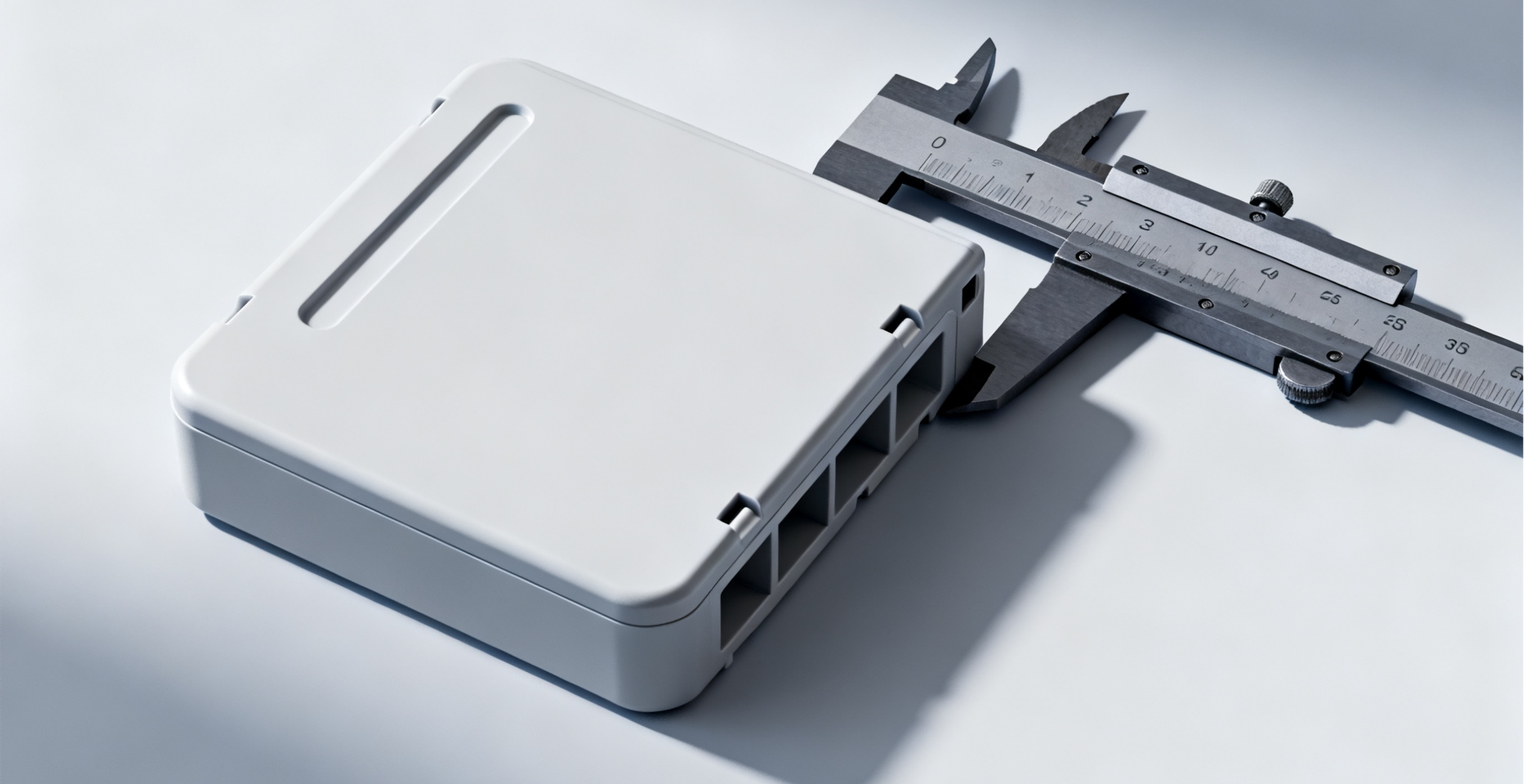
Control the U-arm envelope on the production drawing
The production drawing must communicate the U-shaped arm’s functional envelope. Identify the root transition, leg thicknesses, bend geometry, hook engagement and release opening. Show nearby surfaces that limit movement; they are functional even when they do not touch the latch in the closed assembly.
Distinguish controlled dimensions from design intent. A note saying that the latch must be flexible gives no inspection method. A defined hook position relative to a cover datum, combined with a joint test under stated conditions, is more actionable. Do not apply tight tolerances to the whole enclosure when only a few interfaces determine engagement.
Include the resin grade and permitted substitutions, conditioning, surface requirements at the sliding contact and any assembly restrictions. Record gate or weld-line concerns for tooling review without pretending that the part drawing alone fixes the final flow pattern.
Finally, describe the service operation in the assembly documentation. Identify the intended tool, access direction and sequence for multiple latches. That instruction prevents a successful closure trial from being misread as approval for repeated nondestructive opening. Changes to a mating ledge, cover stiffness or wall rib require a joint review even if the U-shaped arm itself remains unchanged.
FAQ
Can a printed U-shaped latch confirm the molded joint's service life?
A printed assembly is useful for checking where the latch moves, whether the release tool fits and whether the cover can be removed in the intended sequence. Its life result does not automatically transfer to a molded resin. Layer orientation, cure, porosity and surface friction can change failure behavior. Use the printed result to remove geometric mistakes, then qualify recovery and retention using representative molded material and the actual mating interface.
Should a U-shaped latch stay under constant deflection after closure?
That requirement should be deliberate. A joint designed to recover after assembly may lose its intended behavior if the housing holds the arm displaced indefinitely. If preload is needed to control noise or movement, assess the resulting time-dependent force separately from hook engagement. Specify the dwell and environmental conditions used in the evaluation. Do not rely on the initial closing force as evidence that the same preload will remain throughout service.
Can a damaged arm be repaired by adding adhesive?
An adhesive patch changes the joint's stiffness, release behavior and load transfer, and it may be incompatible with the plastic or the service environment. It should not be treated as an equivalent repair to the released molded design. For maintenance, identify whether the enclosure half or another replaceable component must be changed. For production defects, investigate the root cause and disposition the parts through the agreed engineering process rather than concealing the damage.
Conclusion
A compact U-shaped snap joint succeeds when its entire folded path can deform and recover as intended. Root continuity, contact clearance and release access deserve as much attention as the hook. Extra path length cannot compensate for an interfering rib or a service action that cannot be performed inside the product.
Use geometry trials to confirm movement and access, then use representative molded joints to establish force, retention and recovery under the selected conditions. Keep the material grade, mating surface and loaded dwell visible in that evidence. The released requirement should describe both the closed joint and the operation needed to reopen it.
For a latch review, provide 6CProto the enclosure assembly, U-arm section, resin choice and release requirements. These details support a focused discussion of the molded feature and its surrounding tool and assembly constraints.
{“@context”: “https://schema.org”, “@type”: “FAQPage”, “mainEntity”: [{“@type”: “Question”, “name”: “Can a printed U-shaped latch confirm the molded joint’s service life?”, “acceptedAnswer”: {“@type”: “Answer”, “text”: “A printed assembly is useful for checking where the latch moves, whether the release tool fits and whether the cover can be removed in the intended sequence. Its life result does not automatically transfer to a molded resin. Layer orientation, cure, porosity and surface friction can change failure behavior. Use the printed result to remove geometric mistakes, then qualify recovery and retention using representative molded material and the actual mating interface.”}}, {“@type”: “Question”, “name”: “Should a U-shaped latch stay under constant deflection after closure?”, “acceptedAnswer”: {“@type”: “Answer”, “text”: “That requirement should be deliberate. A joint designed to recover after assembly may lose its intended behavior if the housing holds the arm displaced indefinitely. If preload is needed to control noise or movement, assess the resulting time-dependent force separately from hook engagement. Specify the dwell and environmental conditions used in the evaluation. Do not rely on the initial closing force as evidence that the same preload will remain throughout service.”}}, {“@type”: “Question”, “name”: “Can a damaged arm be repaired by adding adhesive?”, “acceptedAnswer”: {“@type”: “Answer”, “text”: “An adhesive patch changes the joint’s stiffness, release behavior and load transfer, and it may be incompatible with the plastic or the service environment. It should not be treated as an equivalent repair to the released molded design. For maintenance, identify whether the enclosure half or another replaceable component must be changed. For production defects, investigate the root cause and disposition the parts through the agreed engineering process rather than concealing the damage.”}}]}