

Explore Injection Molding Assembly & Process Control Guides
A step at a molded part’s seam can prevent seating even when the overall width passes inspection. Before authorizing a tool repair, establish whether the step belongs to the cavity alignment, to local closure behavior, or to a part that changed shape after ejection. These mechanisms call for different evidence and different corrections.
Mold mismatch troubleshooting should begin with a location map and a defined measurement state. Identify the two surfaces forming the step, the side on which each was molded, and the datum relationship that matters to assembly. A photograph of an objectionable seam is useful communication, but it does not establish its cause or size.
Keep flash, mismatch, and broad distortion separate. They can occur together, yet removing excess material may only hide an alignment error. Likewise, forcing a flexible part flat for inspection can create or conceal a step that behaves differently in its free state.
The injection-molding service provides the manufacturing context. The investigation below focuses on local parting-line offset and the evidence needed before a correction becomes part of the released tooling.
Where should mold mismatch troubleshooting start?
Map the step before selecting a repair.
Identify each mating surface, its tool-side origin, the measurement direction and part condition, then compare identified cavities before attributing the offset to guide wear or post-ejection distortion alone.
Choose locations that distinguish a local discontinuity from a general shape change. Mark reference stations on the model or drawing and preserve their identities in photographs and reports. Measuring whichever point looks worst each time makes comparisons difficult and can exaggerate apparent changes.
Record which side stands proud and the direction of the step. A sign convention makes a changing pattern easier to interpret than a list of unsigned heights. Include any nearby flash separately, since a thin fin can affect a contact probe or obscure the true molded surfaces.
Eastman’s copolyester troubleshooting guide treats flashing and distortion as distinct defect categories. Its material-specific guidance is useful context for separating observations, rather than evidence that every resin responds to the same process correction.
Guide wear and cavity alignment
Inspect the alignment system as a complete locating arrangement. Guides, locks, insert seating, local support, and replaceable components can contribute differently to a measured step. A worn guide is a plausible mechanism, but identifying one worn component does not prove it controls the functional offset.
Review the tool’s history and cavity pattern. A step limited to one insert suggests a different investigation from a common directional shift across several locations. Compare the as-built references and recent maintenance changes before deciding whether replacement, reseating, or another correction is justified.
Keep part evidence connected to tool identity. A cavity number, insert revision, and trial sequence let the team test whether an observed pattern follows a particular hardware configuration. Mixed samples remove much of that diagnostic value.
Use the released drawing to define the geometric target. The ASME dimensioning-and-tolerancing framework supports communicating datum relationships, but it does not provide an automatic allowable mismatch for an unspecified molded product. The acceptance limit remains a design requirement tied to function.
Clamping and thermal effects
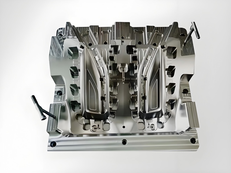
A tool that appears aligned under one condition can behave differently during a molding cycle. Closure, support, local loading, and temperature can affect the relationship between molding surfaces. Review the actual operating arrangement rather than treating a cold static check as a complete explanation of the produced part.
Separate tool behavior from the polymer’s response after release. Material orientation and cooling can change part shape without moving the tool’s reference geometry. Autodesk’s orientation-related warpage guidance identifies molding conditions, thickness, and gate location as relevant influences. It does not establish that a local seam step is automatically a warpage problem.
Document thermal and process state during comparisons. A startup sample, a stabilized trial sample, and a cooled part may answer different questions. Identify the time between ejection and inspection when the part changes appreciably during that interval.
DME’s mold-cooling resources cover cooling design and maintenance. Use that distinction to check both the intended circuit and its condition when investigating a thermal mechanism. Do not compensate an unresolved cooling problem by silently changing the product’s allowed seam geometry.
Measure offset before choosing a correction
Define the reference surfaces and measurement direction before reporting a mismatch value. A height relative to a local surface is different from a distance to a global datum plane. Either can be useful, but the report must show which quantity controls the assembly problem.
Select a method that can resolve both surfaces without being dominated by texture, flash, probe access, or restraint. If the part is flexible, document support and clamping. A method that flattens one region can change the offset elsewhere and make an apparently precise result unrepresentative.
NIST’s uncertainty-analysis framework supports evaluating whether a measurement is suitable for the decision. A proposed repair smaller than the method can reliably distinguish should prompt a measurement review before permanent tool work.
For a trial using prototype injection molding, preserve the observation conditions as part of the approval. A seam accepted under a temporary fixture should not become evidence of an unrestrained production condition without a deliberate comparison.
Seam characteristics and their measurement references
Treat the seam as several potentially independent requirements. Local offset can affect seating, while flash can affect handling and broad shape can affect assembly alignment. A single overall dimension may conceal all three.
Use a table to connect each observation with its reference and consequence. Set the actual limits from the drawing and product function; the entries below organize the decision without supplying generic molding tolerances.
| Observation | Reference | Measurement condition | Decision supported |
|---|---|---|---|
| Parting-line step | Named adjacent surfaces | Direction and support defined | Local seating or appearance |
| Flash | Specified seam zone | Fin thickness and extent separated | Edge acceptance or trimming |
| Global distortion | Functional datum frame | Free or assembly-restrained state | Overall interface fit |
| Tool alignment | Tool-side reference geometry | Documented tool condition | Repair hypothesis |
The table also helps avoid a misleading correction. Trimming a fin can meet the flash requirement while leaving the seating step unchanged. Correcting an insert can remove a local step without resolving the part’s broader distortion. Release each characteristic against the evidence that actually measures it.
Insert-reseating trial with fixed seam stations
Assume an illustrative enclosure shows a seam step of 0.18 mm at station A and 0.04 mm at station B. These are hypothetical observations, not acceptable limits. First confirm that the measurement method can reproduce them under the agreed support and timing conditions.
Compare identified samples from each relevant cavity, keeping material and the baseline process documented. Then inspect the tool references associated with the affected region. If a proposed intervention is to reseat one insert, preserve measurements before and after that intervention while avoiding unrelated changes during the comparison.
Record the correction, tool configuration, process state, measurement setup, and part identities. If several variables must change together, state that the trial demonstrates the combined route rather than isolating one cause. A successful result can support release without proving an unsupported root-cause claim.
After the targeted comparison, confirm the other functional stations and appearance zones. A correction that improves station A may alter neighboring dimensions. The trial should therefore protect the complete affected interface rather than celebrate one reduced step value.
Verify seating, appearance and neighboring interfaces
Assess the corrected part in the conditions that matter to use. A seam can be cosmetically objectionable without affecting fit, or functionally damaging while nearly invisible. Keep these acceptance categories separate so a visual approval does not overrule a seating or sealing requirement unintentionally.
Use identified mating hardware or a controlled assembly surrogate for a fit check. Record whether parts seat freely, require force, or contact at an unintended location. An assembly that is pulled into position by fasteners may conceal a local step while adding stress or changing another interface.
NIST’s measurement-variability discussion distinguishes short-term repeat readings from variation over time. Preserve that distinction when comparing startup, stabilized, and later inspection sessions; measurement drift should not be mistaken for a tooling response.
If a visual master is used, identify its revision and permitted differences. Photographs should show location and viewing conditions, not replace the functional requirement. A retained sample is a useful reference only when the team knows which characteristics were approved and whether any concession was temporary.
Release the repaired tool configuration
Release the correction against defined characteristics and a documented tool configuration. State which seam stations, functional interfaces, and appearance zones were evaluated, and preserve the final measurement method. Keep any remaining limitation visible in the approval record rather than allowing it to disappear into a general statement that the mold was repaired.
For future maintenance, identify the features that need rechecking after insert replacement, alignment work, or a relevant process change. The earlier result belongs to the configuration tested; it should not be applied automatically to materially different hardware.
The rapid-tooling service can support a discussion of repair and revision scope. Provide the measured pattern and the proposed intervention so the manufacturing review addresses the actual mechanism and acceptance target.
Before shipment, close the disposition of suspect trial parts. If a limited batch is accepted under concession, identify its quantity and boundary separately from the permanent release. A temporary cosmetic acceptance should not become an undocumented revision to the part’s functional geometry.
FAQ
Can trimming make a mismatched seam acceptable?
It can address excess material when trimming is permitted and the final geometry is verified. It does not automatically correct the relative location of the two molded surfaces. Review whether material removal changes a seating face, wall, coating, or appearance zone, and define the inspection afterward. If trimming is a temporary disposition, keep it bounded to the approved lot. Avoid treating a smoother-looking seam as proof that the underlying alignment or assembly requirement is satisfied.
Should a mismatch limit be the same around the entire part?
Only when the design justifies that common limit. A hidden clearance region, visible exterior, sealing interface, and locating surface can have different needs. Map the zones and specify how each is evaluated rather than applying an unexplained global number. Keep the limits achievable and inspectable, but do not relax a functional region merely because another area tolerates a larger step. The accepted geometry should follow the product's actual interfaces and observation conditions.
Does a step that changes after cooling prove tool wear?
No. A time-dependent change indicates that material condition, restraint, temperature, or measurement timing needs investigation, but it does not isolate tool wear. Compare identified parts under a controlled method and inspect the relevant tool references separately. Preserve both observations before choosing a repair. A worn component may coexist with post-ejection distortion, and correcting one mechanism may leave the other unchanged. The release decision should describe the demonstrated correction without overstating what caused every observed variation.
Conclusion
A measured seam pattern is a stronger starting point than a repair label. Separate local mismatch, flash, and post-ejection distortion, then compare the part and tool evidence under defined conditions. This makes the proposed correction reviewable and reduces the risk of removing material to hide the wrong defect.
The final approval should connect the repaired configuration with its dimensional, visual, and functional results. Keep the measurement state and cavity identity intact, verify neighboring interfaces, and define what future maintenance must recheck. A single attractive sample is useful evidence, but it does not replace the acceptance record for the affected seam.
6CProto provides injection molding and DFM review. For a mismatch investigation, send the seam map, part drawing, cavity identities, measurement setup, and tool-change history for quotation. Identify the functional surfaces so the proposed trial can distinguish a cosmetic improvement from a verified interface correction.
{“@context”: “https://schema.org”, “@type”: “FAQPage”, “mainEntity”: [{“@type”: “Question”, “name”: “Can trimming make a mismatched seam acceptable?”, “acceptedAnswer”: {“@type”: “Answer”, “text”: “It can address excess material when trimming is permitted and the final geometry is verified. It does not automatically correct the relative location of the two molded surfaces. Review whether material removal changes a seating face, wall, coating, or appearance zone, and define the inspection afterward. If trimming is a temporary disposition, keep it bounded to the approved lot. Avoid treating a smoother-looking seam as proof that the underlying alignment or assembly requirement is satisfied.”}}, {“@type”: “Question”, “name”: “Should a mismatch limit be the same around the entire part?”, “acceptedAnswer”: {“@type”: “Answer”, “text”: “Only when the design justifies that common limit. A hidden clearance region, visible exterior, sealing interface, and locating surface can have different needs. Map the zones and specify how each is evaluated rather than applying an unexplained global number. Keep the limits achievable and inspectable, but do not relax a functional region merely because another area tolerates a larger step. The accepted geometry should follow the product’s actual interfaces and observation conditions.”}}, {“@type”: “Question”, “name”: “Does a step that changes after cooling prove tool wear?”, “acceptedAnswer”: {“@type”: “Answer”, “text”: “No. A time-dependent change indicates that material condition, restraint, temperature, or measurement timing needs investigation, but it does not isolate tool wear. Compare identified parts under a controlled method and inspect the relevant tool references separately. Preserve both observations before choosing a repair. A worn component may coexist with post-ejection distortion, and correcting one mechanism may leave the other unchanged. The release decision should describe the demonstrated correction without overstating what caused every observed variation.”}}]}