
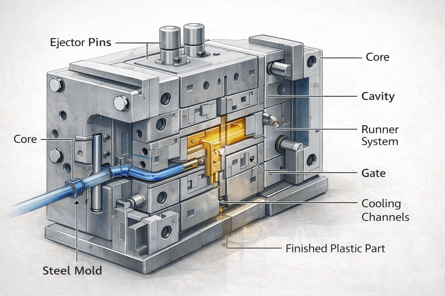





Rapid Tooling Built Around the Mold
Rapid tooling shortens the path from a production-intent CAD model to an injection mold that can be sampled and approved. The work begins with part and mold DFM, then moves through tool design, core and cavity manufacture, fitting, assembly, T0 sampling, measurement, and corrections.
The deliverable is a verified molding tool and its initial sample evidence. If your primary goal is to learn from a small set of production-material parts, see Prototype Injection Molding. If the mold is already approved and you need scheduled repeat batches, see Low-Volume Injection Molding.
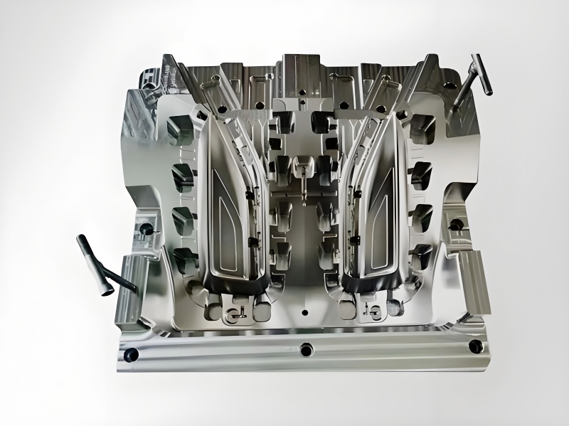
Explore Rapid Tooling Resources
Jump to the information most relevant to your mold or molded-part program.
What Rapid Tooling Covers
A coordinated mold-building program reduces handoffs between part DFM, tool manufacture, trial molding, and corrective work.
Part-to-Tool DFM
Review draft, wall transitions, undercuts, shutoffs, parting line, gate access, ejection, and expected cosmetic surfaces before steel or aluminum is cut.
Core, Cavity, and Components
Machine and fit the mold components required by the approved tool concept, with the process selected around geometry, material, schedule, and expected use.
Trial, Measure, Correct
Run T0 samples, inspect defined characteristics, review molding behavior, and correct the tool where approved changes are required.
From Mold DFM to a Trial-Ready Tool
The workflow keeps tool decisions visible before manufacture and closes the loop with physical samples.
CAD, Resin, and Requirements
Define the molding resin, quantity plan, cosmetic zones, critical dimensions, inserts, texture, and delivery objective.
DFM and Mold Design
Agree parting, gating, ejection, draft, actions, tool material, and the characteristics to inspect during sampling.
Machine, Fit, and Assemble
Manufacture core and cavity details, fit mold components, assemble the tool, and prepare it for the press.
T0 Sample and Correction
Mold initial samples, measure the agreed features, document findings, and complete approved tool corrections.
Rapid Tooling DFM Checklist
The most useful DFM review connects every part feature to a practical mold feature or molding condition.
Part Features That Drive the Tool
- Draft direction and release from core or cavity
- Uniform walls, ribs, bosses, and sink-risk transitions
- Undercuts, side actions, inserts, and shutoffs
- Parting-line position and acceptable witness marks
- Gate location, flow length, weld lines, and venting
- Ejector access and acceptable ejection marks
Information to Include in the RFQ
- 3D CAD plus a drawing for critical requirements
- Exact production resin and any grade or color requirement
- Estimated prototype and production quantities
- Cosmetic surfaces, texture, and finish expectations
- Insert, overmold, assembly, or secondary-operation needs
- Inspection report and sample-approval requirements
Choose Tool Construction for the Program
The fastest tool is not automatically the right tool; construction should match resin, geometry, expected use, surface requirements, and future changes.
| Tooling Decision | Use It to Control | Review Before Approval |
|---|---|---|
| Rapid aluminum tooling | Faster prototype and low-volume mold programs | Resin, geometry, quantity expectation, finish, and change likelihood |
| Durable mold construction | Longer-running or more demanding production programs | Expected use, abrasive materials, maintenance, and production plan |
| Insert or overmold tooling | Metal inserts or multiple-material part construction | Insert retention, loading method, sealing, bonding, and flash control |
| Cosmetic mold surfaces | Gloss, texture, visible parting lines, and appearance | SPI target, grain direction, gate witness, ejector marks, and handling |
T0 Sampling Is the Tooling Proof Point
A mold is not validated only because it closes and cycles. T0 samples connect the manufactured tool to part function and drawing requirements.
Complimentary T0 Parts
Initial parts reveal fill, release, appearance, flash, sink, weld lines, and dimensional behavior under the first molding setup.
Defined Inspection
Measure the drawing characteristics agreed for approval instead of treating every dimension as equally critical.
Controlled Tool Changes
Separate molding-parameter adjustments from physical tool corrections, then confirm the approved result with another sample run.
Quality Gates for Mold Manufacture
Clear approval points keep an urgent tooling schedule from becoming an uncontrolled tooling schedule.
Before Tool Release
Confirm the approved CAD revision, resin, tool concept, gate and parting strategy, cosmetic requirements, critical dimensions, and sample plan.
At Tool Handoff
Confirm sample status, completed corrections, open deviations, approved molding conditions, inspection records, and the next production action.