

A circular lid can snap onto its mating body during a bench trial and still crack during production assembly or lose retention after storage. The ring may have been evaluated at a favorable diameter, the molded material may respond differently from the prototype, or the tooling route may require deformation that the final service joint never experiences.
An annular snap joint uses a circumferential engagement rather than an isolated cantilever hook. Its design must coordinate ring expansion or contraction, interference, entry and retaining faces, material condition and the way the molded part leaves the tool. Installation and demolding are separate deformation events and can impose different constraints.
The specification should therefore define a usable assembly window, not merely a nominal overlap in CAD. The following decisions focus on molded circular joints and their verification. They do not transfer a successful printed fit directly into evidence of molded durability or establish a universal allowable strain for every resin.
How should an annular snap joint divide its ring geometry?
Continuous and interrupted rings deform differently.
A continuous ring distributes deformation around the circumference, while an interrupted ring introduces local bending and segment effects; the selected geometry determines which material and strain model applies.
The Covestro snap-fit design guide distinguishes annular and other snap arrangements. A continuous bead and groove should not be analyzed as several independent straight cantilevers merely because a simple beam equation is convenient. An interrupted design may reduce the continuity constraint but creates local roots and gaps that need their own review.
Draw the engaged section and the ring layout together. Identify which member is intended to deform and whether its surrounding wall can actually move. Nearby ribs, bosses or a rigid insert may prevent the assumed deformation. Also identify whether the joint is intended to release repeatedly or remain assembled. That decision influences the retaining geometry and the tests needed later; a one-time successful insertion is not equivalent to a reusable closure.
At a split or interruption, identify whether the adjoining wall acts as an independent segment or remains coupled to the surrounding shell. That boundary condition changes the assumed flexibility.
Hoop strain and material limits
The material limit must correspond to the actual deformation, temperature and time scale. A resin’s nominal strength is not an allowable repeated snap strain, and a value from another grade or moisture condition should not be substituted without a technical basis. The molded section also differs from a uniform tensile specimen.
For a continuous ring, an initial geometric estimate can relate the required circumferential change to the original circumference. That estimate is useful for identifying a design requiring closer analysis, but it omits local notch effects and restraint from adjacent geometry. An interrupted ring requires a model appropriate to its segment behavior instead.
The snap-fit design reference hosted by MIT discusses geometry and material considerations. Use grade-specific supplier data to establish the permitted design basis. Where retention depends on environmental conditioning, obtain evidence at the relevant state rather than only immediately after molding. A material substitution can change the joint’s force and recovery behavior even when the nominal dimensions remain unchanged.
Retention and insertion forces
The assembly force and the force required to separate the joint are different design outputs. Entry geometry, friction, interference and the stiffness of both mating parts influence insertion. Retaining-face geometry and the deformed state after engagement influence the removal behavior. Changing one face can alter these outputs differently.
Define the acceptable installation method, including alignment and the surfaces that may be supported. A closure that requires an operator to distort an adjacent cosmetic wall has not necessarily demonstrated a controllable production assembly. Likewise, an unusually high removal force is not automatically desirable if the joint must be serviced without damage.
The Covestro guidance on secondary assembly operations emphasizes coordinated joining design. For an annular joint, test the complete mating pair with representative surface and material conditions. Record insertion and retention separately, and distinguish first assembly from repeated use. If the joint remains strained after latching, a short-term retention result should not be used as evidence of long-term holding performance without an appropriate conditioning assessment.
If installation uses a press or fixture, control the contact surfaces and alignment during the trial. A hand-installed favorable sample can conceal the loading imposed by the production assembly method.
Tooling and demolding constraints
A bead or groove can create an undercut relative to the selected mold opening direction. The tool must either provide a suitable release mechanism or rely on an approved deformation route. The fact that the finished closure can snap together does not establish that the molding can be stripped from the tool without damage.
Review the parting line, core arrangement and the state of the part during ejection. The direction of deformation may differ from assembly, and local temperatures and support can affect the result. A tooling proposal should make the assumed release behavior explicit before the cavity is cut.
The Covestro TPU ejector-mark guide relates ejection problems to tool and process conditions for that material family. Its recommendations are material-specific and do not approve a particular annular undercut in another resin. In an injection molding DFM review, identify which ring features are fixed by function and which can be changed to provide a practical release route. Tool feasibility and joint performance need to be resolved together, with neither assumed from the other.
Ring geometry and material decision table
A selection table is useful when it identifies the next necessary evidence. It should not rank continuous and segmented rings as universally better or worse. Their relative suitability depends on the required seal, appearance, service access and permitted deformation.
Evaluate the complete circular interface, including how diameter variation and out-of-roundness can concentrate engagement. A nominal section alone cannot show every circumferential contact condition.
| Design choice | Main consequence | Evidence needed | Unresolved risk |
|---|---|---|---|
| Continuous engagement | Circumferential deformation is constrained | Appropriate ring model and representative pair tests | Local restraint or ovality changes the assumed behavior |
| Interrupted engagement | Segments introduce local bending and roots | Segment strain and retention distribution | Uneven contact among segments |
| Repeated release | Recovery matters after each cycle | Conditioned insertion and removal records | Damage or permanent set accumulates |
| Permanent closure | Service disassembly may be destructive | Retention and intended-use validation | Assembly damage remains hidden |
Use the selected resin’s processing and property documentation alongside this comparison; geometry labels do not supply allowable strain values.
Dimensioned ring section and assembly example
Assume an illustrative ring must increase its diameter from 40.0 mm to 40.4 mm during an idealized uniform expansion. The corresponding circumferential strain estimate is the diameter change divided by the original diameter: 0.4/40.0 = 0.01, or 1%. This is a geometric estimate under explicit uniform-deformation assumptions, not a permitted strain for a particular material.
The real section may experience nonuniform deformation, local bending and contact stresses. Show bead height, groove position, wall transitions and the relevant diameter limits on the drawing. Include the supported assembly direction so the test does not use an unrealistic clamping arrangement.
The Autodesk snap-fit modelling tutorial helps distinguish modeled engagement from the separate validation task. A CAD feature creates geometry; it does not approve the strain estimate or demolding behavior. If the available section cannot meet the material’s approved deformation limits, revise the geometry or joining concept before treating a successful hand assembly as a design release.
Dimension both mating members at the conditions used for acceptance. Specifying only the expanding ring leaves the interference window unresolved when the receiving groove or bead also varies.
Conditioned retention and acceptance observations
The test plan should identify what is being retained and under which conditions. A closure can experience axial pull, handling loads or repeated removal, and those conditions do not all produce the same failure mode. Include the actual mating part and any relevant retained seal or insert in the test configuration.
Measure force through a defined alignment and loading method. Record cracking, whitening, permanent set, partial engagement and changes in seating as well as the peak force. A high reading caused by misalignment may represent an assembly problem rather than improved retention.
Use dimensional acceptance requirements to connect test results to the measured ring geometry. Test representative limiting combinations when the joint depends on a narrow interference window. One favorable pair cannot establish performance across the full diameter range. Where storage or environmental exposure matters, define conditioning before testing and keep its duration and state in the record. The result should support the actual service claim, without implying a broader lifetime than the test addresses.
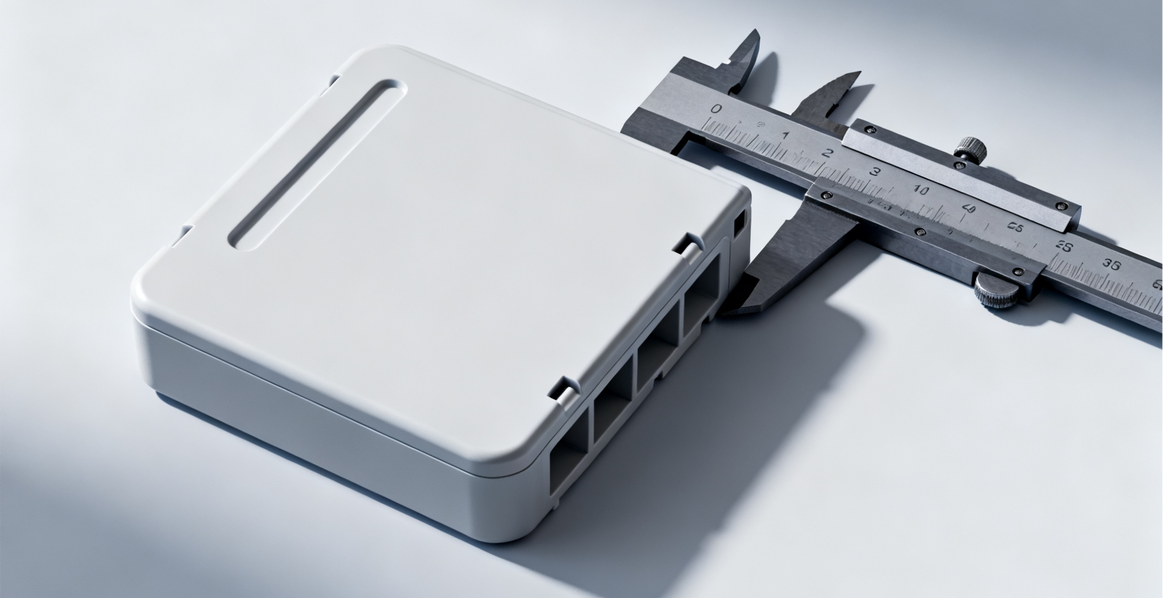
Production drawing notes for the circular joint
The drawing package should identify the resin grade, mating interface, critical diameter limits and the intended assembly and release behavior. Specify where flash, gate vestige or ejector witness can interfere with engagement. Those process-related features deserve acceptance criteria rather than being left as cosmetic matters unrelated to the joint.
Keep the ring’s critical transition geometry coordinated with the tool release design. If the molder proposes a different undercut, segment gap or wall transition, assess insertion and retention again before accepting the change. A tooling adjustment can improve demolding while altering the closure’s operating behavior.
For prototype development, state which questions the current material and process can answer. A geometry prototype may support packaging or access review while leaving conditioned retention unverified. Carry those limits into the production handoff. The final specification should identify the approved molded route and the joint evidence, not rely on the memory that an earlier sample snapped together.
When tool maintenance changes the bead or groove, compare the resulting molded interface with the approved test configuration. A cavity repair should not inherit retention approval without that geometry check.
FAQ
Is a torsion snap joint the same as an annular joint?
No. A torsion arrangement obtains its spring action through twisting a member, while an annular joint uses a circumferential engagement whose deformation may involve hoop expansion or local segment bending. The appropriate model and material checks differ. A designer can combine mechanisms, but the resulting joint should be evaluated according to how it actually deforms rather than classified from its outside appearance alone. The ring label does not justify using a torsion formula.
Can an annular snap joint also provide a seal?
It can retain components of a sealing arrangement, but engagement alone does not establish leakage performance. The sealing surfaces, retained seal, material condition and dimensional variation must be evaluated together under the specified exposure. A retention test and a leakage test answer different questions. If a ring is interrupted for flexibility or tooling reasons, assess the effect on the intended seal rather than assume the closure's successful assembly preserves the original sealing function.
Should whitening after assembly be accepted?
Whitening is an observation that needs assessment against the material, geometry and intended use. It may indicate a local deformation condition that warrants investigation, but appearance alone cannot quantify remaining life or prove failure. Record its location, compare the actual assembly method and inspect for other damage. Acceptance should follow an approved criterion supported by the relevant joint validation, rather than be decided solely by whether the closure still holds immediately after installation.
Conclusion
An annular joint is ready for release when its deformation model, material limits, tooling release and conditioned retention evidence describe the same geometry. Nominal interference is only one input to that agreement.
Keep the circumferential behavior distinct from a cantilever latch calculation, and treat demolding as its own load event. Then validate the mating pair across the required dimensional and environmental window. This exposes a joint that works only in a favorable prototype state before that state is mistaken for a production capability.
6CProto’s molding and DFM workflow can support review of the circular interface and tooling constraints. Send the mating sections, resin specification and insertion and retention requirements for quotation, identifying the release and conditioning tests needed for approval.