

Explore Injection Molding Assembly & Process Control Guides
A latch can assemble cleanly on the first day and lose useful retention while the enclosure remains closed. Increasing the initial insertion force may make assembly harder without solving the long-term mechanism. The important distinction is how far the latch bends during installation and how much deflection remains after it seats.
Snap fit creep must be evaluated with the locked geometry, material condition, temperature, and time under load defined. Under sustained stress, a polymer can develop additional strain; under approximately fixed deflection, its stress can relax. A retained hook can therefore lose contact force without showing an obvious fracture.
The design objective is to carry service loads through an appropriate contact geometry while minimizing unnecessary sustained bending. That does not mean every snap should be completely unloaded when closed. It means the remaining deflection and its purpose should be deliberate, with evidence for the expected environment and duration.
The injection-molding service provides the manufacturing context for the joint. The discussion below concerns molded latch retention over time; a printed prototype’s first assembly feel is not a substitute for representative material and conditioning evidence.
How does snap fit creep differ from assembly strain?
Assembly deflection is brief; locked deflection persists.
Check the peak strain needed to pass the hook separately from the residual bending after seating, because short assembly survival does not establish sustained retention in the service environment.
During assembly, the hook travels over a lead-in and may return toward its free position after engagement. That return is valuable: it reduces the deformation maintained while the joint remains closed. A tolerance stack that prevents the return can leave a nominally relaxed design continuously loaded.
The Covestro snap-fit design guide distinguishes the geometric and material considerations needed for snap connections. Use grade-appropriate data and the actual beam shape rather than assigning one allowable strain to all polymers or every latch configuration.
Inspect the locked contact arrangement. A hook that retains by a positive bearing surface behaves differently from a friction-dependent latch whose force comes primarily from continuous bending. Identify which mechanism carries the separating load, then examine what relaxation would change. A high insertion-force measurement alone does not answer that question.
Temperature and time under load
A retention requirement needs a time and environment attached to it. A room-temperature pull test immediately after assembly describes a different condition from a closed enclosure stored warm for an extended period. Identify expected storage, operation, moisture, and chemical exposures before selecting the validation condition.
Use the material supplier’s grade-specific time-dependent information where available. Short-term tensile modulus is not a universal predictor of creep or stress relaxation. Reinforcement, moisture, processing, and temperature can change behavior, and a nominal polymer family does not define the required design data.
The snap-fit design document hosted by MIT provides technical context for snap-joint design and material response. It should guide the questions asked, not become a substitute for evidence on the actual molded grade and geometry.
Avoid declaring an arbitrary elevated-temperature dwell equivalent to years of use without a justified model. An accelerated condition can reveal a weakness while also introducing a different mechanism. Record the exposure and the resulting retention directly, and state any extrapolation method separately with its assumptions and limits.
Stress relaxation in the latch
When the mating parts hold the latch at roughly fixed deflection, the polymer’s resisting stress can decrease over time. The visible geometry may change little because the assembly constrains it. Retention can still fall if it depends on that resisting force or on friction at the contact.
If the latch instead carries a sustained external force, additional deformation can alter engagement, contact location, or clearance. Real joints may combine these conditions as neighboring walls flex and contact surfaces move. Model the complete load path rather than assuming the beam alone determines the result.
Covestro’s secondary-operations guidance for plastics places snap connections among several assembly methods. A screw, clip, or separate spring may be appropriate when service retention requires a mechanism the proposed plastic latch cannot maintain under its environment.
Review tolerance extremes in the locked state. A small nominal interference may become a much larger sustained deflection when both mating dimensions move unfavorably. Conversely, a relaxation-resistant beam does not help if the hook’s engagement disappears at the opposite extreme of the same stack.
Retention checks after conditioning
Measure retention in the state that matters to the requirement. If the product must hold while warm and assembled, a test performed only after complete cooling and disassembly can miss the relevant response. Define whether the test concerns in-service load, recovered performance, or permanent set.
Keep installation history controlled. Repeated assembly can wear the contact or damage the root, creating a different mechanism from sustained closure. Use separate specimens or a planned sequence when the investigation needs to distinguish first assembly, dwell, cycling, and recovery.
NIST’s measurement-variability discussion supports separating short-term repeat readings from changes across time. For retention testing, preserve grip arrangement, pull direction, speed or loading method, and the point at which the force is evaluated.
Record both load and failure mode. A lower force caused by contact wear is different from a beam that has relaxed while the hook remains intact. Photograph the engagement and root condition, and retain actual force-displacement observations where they help distinguish slip, unlatching, fracture, or deformation of the surrounding housing.
Material and joint choice comparison table
Compare joint strategies by the mechanism that preserves retention, not by a generic strength ranking. Material selection and geometry must be considered together. A nominally stiff grade can still be unsuitable if its locked deflection, environment, or root geometry creates an unvalidated sustained strain.
The table lists design directions and the evidence each requires. It does not assign universal life, allowable strain, or superiority to a resin family or a fastening method.
| Joint arrangement | Retention mechanism | Time-dependent concern | Useful validation |
|---|---|---|---|
| Relaxed hook after seating | Positive geometric engagement | Engagement margin and housing movement | Conditioned separation and stack extremes |
| Continuously bent latch | Beam force and contact | Stress relaxation | In-state retention after dwell |
| Friction-dependent snap | Normal force and friction | Relaxation, wear, contamination | Environmental and cycling sequence |
| Separate spring or fastener | Dedicated retention element | Interface and assembly behavior | System-level retention and service checks |
Evaluate these choices with the product’s assembly and service needs. A mechanism that improves long-term retention may add parts or access requirements, while a simple molded hook can remain appropriate when its geometric engagement and conditioning evidence are sufficient.
Dimensioned joint section and assembly sequence
Assume an illustrative rectangular cantilever has length L = 12 mm, thickness t = 1.2 mm, assembly deflection 0.8 mm, and locked deflection 0.15 mm. For an ideal small-deflection cantilever with a tip load, the root surface-strain estimate is approximately 1.5t times deflection divided by L squared.
The assembly estimate is 1.5 × 1.2 × 0.8 / 144 = 0.010, or 1.0%. The locked estimate is 1.5 × 1.2 × 0.15 / 144 = 0.001875, or approximately 0.188%. These are geometric elastic estimates under stated assumptions, not allowable strains, creep predictions, or material approval values.
Actual latch behavior can differ because of taper, root compliance, large deflection, contact position, and housing flexibility. The calculation’s purpose is to separate the two deflection states and identify the inputs that need checking on the molded joint.
Use the prototype route to examine access and engagement where useful, then confirm time-dependent retention with representative material and processing. A mockup can reveal an impossible assembly path without proving sustained performance.
Validation loads and acceptance observations
Define the service retention requirement independently from insertion-force preferences. The test should specify the separating load or displacement condition, environment, dwell, assembly history, and the acceptance observation. Include the engagement margin and any permitted permanent deformation when those affect function.
Choose specimens that represent the relevant tolerance and process conditions. A set drawn only from the most favorable dimensions cannot show how the locked deflection behaves at the stack extremes. Keep cavity and material identity where they may explain different responses.
NIST’s uncertainty-analysis framework supports reviewing whether the measurement system can distinguish the acceptance margin. For a small latch force, grip friction, fixture compliance, and loading alignment can matter as much as the sensor’s displayed resolution.
Preserve failure observations even when the measured load exceeds the threshold. A latch that passes once by damaging its engagement surface may not meet a repeated-service requirement. Conversely, an intentionally nonserviceable joint needs a different acceptance definition from a cover expected to be opened and closed throughout use.
Drawing notes for the production joint
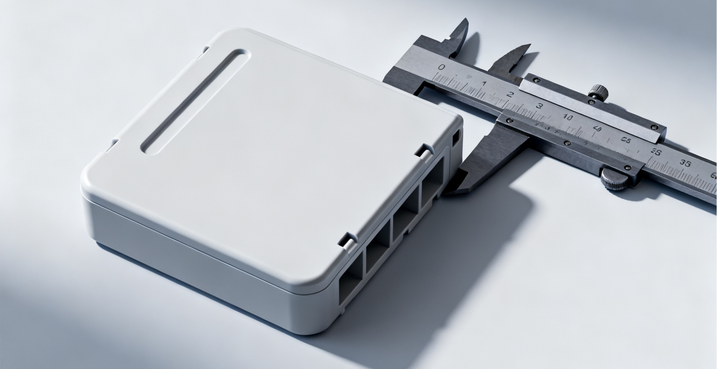
The production definition should show the free shape, assembly path, locked engagement, and the surfaces that carry separation load. Include the material grade and conditioning assumptions used in validation. Avoid a note that merely says “no creep”; it does not define an observable acceptance requirement.
Dimension the relationship between latch and mating feature so the locked-state tolerance stack is reviewable. The ASME geometric-dimensioning framework can support that communication, but the drawing must still state the actual feature requirements and accepted condition. Mark critical root and contact regions where unreviewed changes could alter behavior.
Use the standards-and-tolerances resource to frame the dimensional discussion without assuming a generic tolerance controls retention. Include the agreed conditioned-retention test as a separate requirement when it is necessary.
At release, retain the validated geometry, material identity, and test configuration together. Changes to wall support, root shape, reinforcement, color package, or processing assumptions should be reviewed for their effect on the demonstrated retention mechanism before the previous result is reused.
FAQ
Can a latch recover its retention after being opened and cooled?
Some deformation or force response may recover, but the amount and timing depend on the material, exposure, geometry, and any damage or wear. Recovery is a separate observation from retention while the product remains assembled in service. Define both if they matter, and preserve the interval between opening, cooling, and retesting. A recovered bench result should not be used to claim that the closed joint maintained its required force throughout the exposure.
Does adding a thicker snap beam always improve long-term retention?
No. A thicker beam can increase stiffness and insertion force while also changing the strain required for a specified deflection. It may transfer more load into the housing or mating feature without resolving the sustained locked deformation. Review the complete geometry and tolerance stack before changing thickness. A longer compliant path, reduced locked interference, positive engagement, or a different retention mechanism may address the actual problem more directly, but each option needs validation.
Can an accelerated dwell test replace a full service-life claim?
Only when the acceleration approach is technically justified for the relevant material and failure mechanism. A severe condition may reveal a useful weakness without providing a reliable time conversion to service. Document temperature, humidity, load or constraint, specimen history, and the model used for any extrapolation. If no validated relationship exists, report the test as evidence for its actual exposure and acceptance condition rather than labeling the result as an equivalent number of service years.
Conclusion
Long-term latch retention depends on the deformation that remains after assembly and the mechanism that carries separation load. Separate short assembly strain from sustained bending, then evaluate stress relaxation, engagement margin, and surrounding-wall movement under the actual environment and duration.
The useful evidence is a defined conditioned-retention result with material, geometry, tolerance state, and test configuration preserved. A strong first insertion, an intact hook, or recovery after cooling cannot independently establish retention during service. Keep the elastic estimate in its proper role as a design-screening calculation, and use representative molded joints for the time-dependent decision.
6CProto supports injection molding and DFM review within its manufacturing scope. To review a retention-sensitive joint, send the latch section, mating geometry, resin grade, service environment, and conditioned-test requirement for quotation. Identify both assembly and locked deflections so the discussion addresses the joint’s sustained behavior rather than only its first assembly.
{“@context”: “https://schema.org”, “@type”: “FAQPage”, “mainEntity”: [{“@type”: “Question”, “name”: “Can a latch recover its retention after being opened and cooled?”, “acceptedAnswer”: {“@type”: “Answer”, “text”: “Some deformation or force response may recover, but the amount and timing depend on the material, exposure, geometry, and any damage or wear. Recovery is a separate observation from retention while the product remains assembled in service. Define both if they matter, and preserve the interval between opening, cooling, and retesting. A recovered bench result should not be used to claim that the closed joint maintained its required force throughout the exposure.”}}, {“@type”: “Question”, “name”: “Does adding a thicker snap beam always improve long-term retention?”, “acceptedAnswer”: {“@type”: “Answer”, “text”: “No. A thicker beam can increase stiffness and insertion force while also changing the strain required for a specified deflection. It may transfer more load into the housing or mating feature without resolving the sustained locked deformation. Review the complete geometry and tolerance stack before changing thickness. A longer compliant path, reduced locked interference, positive engagement, or a different retention mechanism may address the actual problem more directly, but each option needs validation.”}}, {“@type”: “Question”, “name”: “Can an accelerated dwell test replace a full service-life claim?”, “acceptedAnswer”: {“@type”: “Answer”, “text”: “Only when the acceleration approach is technically justified for the relevant material and failure mechanism. A severe condition may reveal a useful weakness without providing a reliable time conversion to service. Document temperature, humidity, load or constraint, specimen history, and the model used for any extrapolation. If no validated relationship exists, report the test as evidence for its actual exposure and acceptance condition rather than labeling the result as an equivalent number of service years.”}}]}