

Explore Injection Molding Assembly & Process Control Guides
A latch can work in a CAD assembly and still require an unexpected slide in the mold or break during ejection. Injection molding snap fit design must connect the product’s assembly motion with the tool’s opening motion. Those directions are related, but they are not necessarily the same.
The priority is to decide how the hook is formed and released, then assess how the molded arm behaves during closure and service. A prototype that snaps together confirms only part of that problem. It may not reproduce the root structure, flow orientation or ejection strain of the final molded component.
This guide concerns the release of an injection-molded latch into a repeatable production route. It focuses on hidden undercuts, material-dependent deflection, weld-line location and assembled validation. Particular folded, annular or torsional mechanisms require their own geometry analysis rather than one universal beam rule.
Within the injection molding review, the snap feature should be considered alongside parting lines, core access, gate location and ejection. A narrow latch cannot be approved independently of the wall that supports it. The useful result is a coordinated part-and-tool definition, not a hook added to an otherwise finished model.
Where should injection molding snap fit design begin?
Tool release and joint release need separate checks.
Review injection molding snap fit design in the mold-opening direction as well as the assembly direction, then decide how every hook undercut is formed, released and inspected.
Project the hook against the proposed tool draw. A ledge that retains the product cover may trap the molded part on a core. Depending on geometry, the solution may involve an opening through the wall, a parting-line arrangement, a moving tool element or a deliberately qualified elastic-release approach.
Do not assume that the arm can simply strip from the tool because it flexes during assembly. Its temperature, support and direction of loading during ejection differ from service. BASF's molding-design example explicitly examines undercuts and injection location as part of manufacturability, illustrating why these features belong in the tool review.
Show steel access to the retaining face and clearance for moving tooling. Check that the chosen solution does not leave an unacceptable witness line on the contact surface or create a fragile tool detail. Resolve these matters before reducing the hook to meet an assembly-force target; a geometry change can alter both retention and the tool concept.
Check beam geometry against material-dependent travel
Allowable latch travel depends on geometry and material response. A longer arm can reduce strain for a given tip displacement in a suitable beam model, while local thickness, taper and root support change the distribution. A short thick hook on a flexible wall is not equivalent to the same hook on a rigid wall.
BASF's snap-fit application description identifies beam dimensions, entry and return angles, deflection and strain as connected inputs. Use an appropriate model for the actual mechanism and resin. A single published allowable strain should not be transferred between grades, reinforcement levels or conditioning states.
Check the maximum required travel from the complete tolerance stack. The nominal undercut is only one contributor: mating-wall position, cover alignment and local interference can increase the demanded movement. Include the supporting wall in an analysis when its flexibility is significant.
The initial calculation should identify a feasible region, not certify a final latch. Contact friction and molded geometry influence insertion and release forces. Confirm the design with representative parts, especially when repeated opening, warm service or prolonged loaded dwell makes a short-term elastic estimate insufficient. Keep the assumptions beside the calculated result in the engineering record.
Connect root behavior with flow direction and weld lines
The molded root has a process history. Melt flow around an opening can reunite near the latch, and reinforcement can orient differently through the arm and supporting wall. That location may experience the highest strain during assembly, making flow and joint design inseparable.
Use the gate and flow review to identify a plausible weld-line location, then assess its consequence for the actual resin and loading. BASF's injection-molding simulation overview includes filling pattern, fiber orientation and warpage among the predicted outputs. These outputs support a design investigation; they are not proof that every molded part has the assumed local properties.
Avoid placing an unqualified weld line at a highly loaded root solely to preserve a convenient gate location. Alternatives may change the flow path, root geometry or part orientation in the tool. Each can affect other surfaces, cycle requirements or dimensional behavior and should be assessed across the complete component.
During sampling, inspect the actual root condition and compare it with the simulation assumptions. A visual line alone does not quantify strength, while an invisible line does not prove its absence. Where the joint’s function is sensitive, representative mechanical testing is more informative than a cosmetic inspection alone.
Test closure, retention and intentional release separately
Assembly testing should reproduce the product’s restraint and loading direction. A latch pressed by hand on an unsupported loose part may behave differently when the enclosure is fastened around a seal or constrained by internal components. Include those interactions when they affect closure or release.
Record insertion, retention and intentional opening as separate operations. A latch can retain strongly while being damaged by the specified service tool, or close easily while retaining inadequate engagement. Define which failure modes are acceptable and which indicate a design or molding problem.
Covestro's secondary-operations overview places joining within a broader plastics-processing context. For a snap assembly, this means the mating surface, assembly sequence and component condition belong in the test description rather than being treated as incidental details.
Test selected dimensional extremes and representative molded variation. Include relevant environmental conditioning and any loaded dwell before opening. Do not call a short closure trial a durability qualification. The prototype stage is valuable for access and motion studies, while the production-latch decision needs evidence that represents the final material and molded feature.
Compare material fidelity with the joint requirement
Choose the material and mechanism together. A resin suitable for a stiff enclosure is not automatically suitable for a compact flexible arm. Reinforcement, temperature response, moisture and contact behavior can alter the balance between insertion force and retention.
| Joint requirement | Material question | Geometry or tooling consequence | Evidence |
|---|---|---|---|
| One-time closure | Can the arm survive the assembly event? | Required travel and hook engagement | Representative assembly trial |
| Repeated service | Does recovery persist after cycling and dwell? | Accessible release and controlled strain | Conditioned repeated-operation test |
| Stiff reinforced housing | How does local orientation affect the root? | Gate, wall and arm layout | Flow review and molded test pieces |
| Cosmetic contact region | Will sliding or release mark the surface? | Parting line and tool witness placement | Actual mating-surface evaluation |
Covestro's snap-fit guide distinguishes mechanism types and material-dependent design considerations. Its examples should not be treated as a guarantee for a different grade or geometry. Specify the exact resin and permitted substitutions, then evaluate the chosen joint under conditions that represent its intended use. A generic label such as engineering plastic does not provide enough information to release a strain-sensitive feature.
One section for hook travel and tool-opening access
Assume a hypothetical enclosure hook overlaps its mating ledge by 0.6 mm in the closed state. The worst stated dimensional combination adds 0.25 mm to the displacement needed for passage, and the design includes 0.15 mm of deliberate travel clearance. The required geometric movement is therefore 0.6 + 0.25 + 0.15 = 1.00 mm.
That sum defines a displacement target, not allowable deflection. The arm geometry, supporting wall and resin must accommodate it without unacceptable strain or permanent set. Evaluate the actual assembly contact rather than applying the entire sum at an arbitrary point on the hook.
Now add the mold-opening direction to the section. If the hook’s retaining face is trapped, identify how the tool forms and releases it. A window behind the hook might provide steel access, but it also changes wall stiffness and the flow path. A slide might preserve the wall but add another tool interface.
Select the tool concept and latch geometry together, then check the release sequence and test the molded feature. Keeping both motions on the same section prevents an assembly improvement from creating an unresolved molding problem later in the release.
Validate molded variation and observe the failure mechanism
Validation loads should follow the real joint function. Define the support fixture, loading direction, rate where relevant, environmental condition and criterion for successful engagement. Record displacement as well as peak force when the mechanism’s movement provides useful diagnostic information.
Inspect the root, hook and mating ledge after the test. Whitening, cracking, permanent offset or wear can explain a force change, but each observation requires interpretation in the chosen material. Do not accept or reject every visible change using a rule borrowed from another resin.
BASF's molding troubleshooting guide provides a process-focused basis for investigating molded defects. Use it to avoid attributing every failure to nominal CAD dimensions. Short filling, flash, local damage or an inappropriate processing condition can invalidate an otherwise sensible joint design.
The acceptance record should connect dimensional checks with the sampled assemblies and molding condition. If tooling is revised, identify which tests must be repeated. A previous pass on a different gate arrangement or root geometry is not automatically evidence for the changed part, even when the external enclosure dimensions remain the same.
Release the latch geometry with its material and test basis
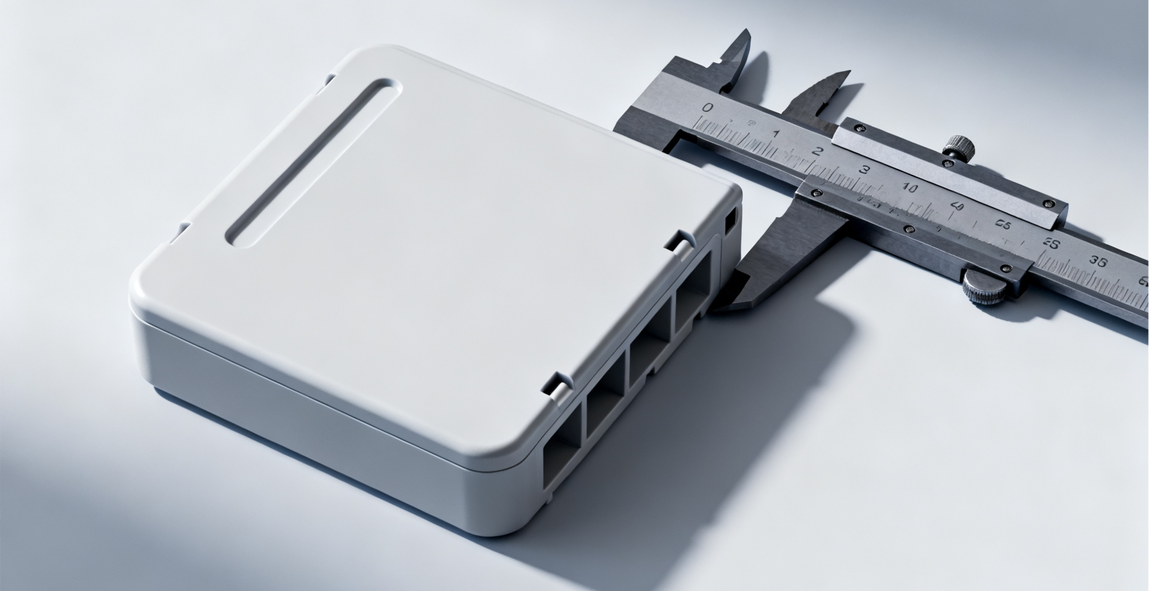
The production drawing should control the interfaces that determine the joint’s motion and final engagement. Identify root geometry, hook position, mating ledge, release access and any surface that can limit travel. Show the datum relationship between the enclosure halves rather than tolerancing each hook without an assembly reference.
Communicate the exact material grade, surface requirements and any permitted substitutions. Put the molding and assembly requirements in coordinated documents: the drawing establishes the product, while the approved tool and process records establish how the critical feature is made.
State the intended life category and test conditions without inventing a universal cycle requirement. If the latch is not intended for nondestructive reopening, make that distinction clear in the product’s assembly definition. If it is serviceable, specify how it is released without relying on an undocumented shop tool.
For handover, preserve sample identification and the accepted force or retention evidence. A replacement tool insert, gate change or resin substitution can change the local latch behavior even when a broad dimensional report still passes. Reviewing those changes against the original mechanism is the practical route to a repeatable molded joint.
FAQ
Can a snap-fit latch be moved to another mold cavity unchanged?
The nominal geometry can remain unchanged while local filling, cooling, ejection and dimensional behavior differ. Treat the receiving cavity as a new source of evidence for the critical feature. Compare root condition, engagement dimensions and assembly performance using representative parts. This does not mean every transfer requires the same test program; the scope should follow the joint's sensitivity and the changes involved. Preserve cavity identification where it is needed to interpret the results.
Is lubricant an acceptable way to lower insertion force?
Only when the material, product environment and assembly requirements permit the selected lubricant. It can change contact friction, retention, contamination risk and later finishing or bonding. A lubricated trial should not be presented as evidence for a dry production joint. If lubrication is part of the released process, specify its application and evaluate both closure and service behavior. Do not use it to conceal excessive required travel or a damaged molded root.
Should the latch be inspected before or after painting?
Use the state required for function. Pre-paint checks can establish molded geometry, while the finished joint must also account for coating on sliding or retaining surfaces where applicable. Coating can alter clearance, friction and visual acceptance. Define masked areas and final assembly checks when necessary. A passing uncoated sample is not sufficient evidence for a painted interface if the finish changes the geometry or the force required for closure and release.
Conclusion
A production snap joint must be moldable, assemblable and verifiable. The tool-opening path establishes how the hook can be formed and released; the assembly path establishes required travel; the material and local process history establish whether the feature can perform that motion repeatedly.
Resolve hidden undercuts before tooling commitment, and keep flow direction and weld-line sensitivity attached to the root assessment. Use prototype assemblies to remove access mistakes, then use representative molded parts for the decisions that depend on local properties and production variation. The acceptance record should describe the actual joint and its test state rather than rely on a click or a nominal beam calculation.
For a focused latch review, share the assembly section, proposed resin, tool-opening direction and required release behavior with 6CProto. These inputs connect the feature to the manufacturing route before the tool definition is fixed.
{“@context”: “https://schema.org”, “@type”: “FAQPage”, “mainEntity”: [{“@type”: “Question”, “name”: “Can a snap-fit latch be moved to another mold cavity unchanged?”, “acceptedAnswer”: {“@type”: “Answer”, “text”: “The nominal geometry can remain unchanged while local filling, cooling, ejection and dimensional behavior differ. Treat the receiving cavity as a new source of evidence for the critical feature. Compare root condition, engagement dimensions and assembly performance using representative parts. This does not mean every transfer requires the same test program; the scope should follow the joint’s sensitivity and the changes involved. Preserve cavity identification where it is needed to interpret the results.”}}, {“@type”: “Question”, “name”: “Is lubricant an acceptable way to lower insertion force?”, “acceptedAnswer”: {“@type”: “Answer”, “text”: “Only when the material, product environment and assembly requirements permit the selected lubricant. It can change contact friction, retention, contamination risk and later finishing or bonding. A lubricated trial should not be presented as evidence for a dry production joint. If lubrication is part of the released process, specify its application and evaluate both closure and service behavior. Do not use it to conceal excessive required travel or a damaged molded root.”}}, {“@type”: “Question”, “name”: “Should the latch be inspected before or after painting?”, “acceptedAnswer”: {“@type”: “Answer”, “text”: “Use the state required for function. Pre-paint checks can establish molded geometry, while the finished joint must also account for coating on sliding or retaining surfaces where applicable. Coating can alter clearance, friction and visual acceptance. Define masked areas and final assembly checks when necessary. A passing uncoated sample is not sufficient evidence for a painted interface if the finish changes the geometry or the force required for closure and release.”}}]}