

Explore Injection Molding Assembly & Process Control Guides
A molded latch can have the intended dimensions and still break where two flow fronts met near its root. Moving the visible line elsewhere is useful only if the new flow pattern also protects the load path and preserves filling, venting and dimensional control. A cosmetic improvement alone does not qualify the latch.
Injection molded snap fit weld lines need a joint review of filling behavior and assembly deformation. The important question is where the meeting front lies relative to the region that bends, the direction of the applied load and any local notch. The exact resin grade, reinforcement and conditioning state also matter.
This article addresses that flow-to-function relationship. It leaves basic snap-fit sizing to the calculation guide and treats simulation as a way to target trials, rather than a substitute for molded-part evidence. A line that is absent from a plot may still be present on the part.
Include the latch, adjacent openings and proposed gate locations in the injection-molding review. Those surrounding features often determine the flow split. Reviewing only the isolated hook removes the geometry that creates the weld line and can lead to an ineffective tooling change.
Where will the flow split around the snap-fit feature?
Trace the split through the surrounding geometry.
Openings, ribs and local thickness transitions can divide the melt front before it reaches the latch, so evaluate the complete fill path rather than the hook geometry alone.
Mark the gate, obstructions and likely meeting regions on the model. A hole beside the beam can send material around both sides and create a meeting front downstream. Multiple gates can produce a different meeting pattern even when the latch itself has not changed.
Autodesk's weld-and-meld-line guidance relates line formation to converging flows and identifies gate placement and thickness as ways to move the fill pattern. The relevant design decision is whether that change moves the meeting region away from the mechanically demanding part of the latch.
Compare the predicted path with short-shot observations from a controlled trial. Preserve cavity and condition identity so the physical progression can be compared with the simulation. Do not infer a flow path from a single finished-part photograph when surface appearance is faint or the visible line ends before the critical section.
Root strain and weld-line location
The root carries substantial bending demand during assembly, so a meeting front in that region deserves particular attention. Map the deformed shape and the tensile side of the root rather than measuring only the distance from a visible line to the hook tip.
The Covestro snap-fit design guide discusses the cantilever root and the importance of avoiding local stress concentration. That mechanical context identifies where the flow review should concentrate; it does not supply a universal weld-line strength reduction factor for every resin or geometry.
Consider the orientation of the line through the section. A surface trace does not fully describe the internal interface or the reinforcement orientation in a filled material. A smooth-looking root can therefore remain vulnerable under the actual assembly motion.
Keep geometry and material changes distinguishable during investigation. If a larger root radius and a moved gate are introduced together, the improved result cannot be attributed confidently to either change alone. A deliberate trial sequence can establish which design and process controls are needed to reproduce the accepted latch.
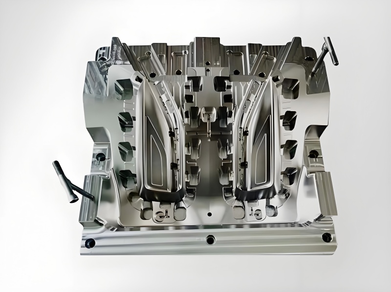
Gate and venting alternatives
Compare gate alternatives against both the root load path and the rest of the component. Moving a gate can shift the line while changing packing, orientation, gate vestige and warpage. A satisfactory latch solution must preserve those other requirements.
Venting needs attention at the meeting region because trapped gas can interfere with the joining fronts. Use the selected resin’s processing and tooling guidance when defining vent details. Avoid a universal vent depth or a blanket instruction to increase pressure; a change that helps one defect may introduce another.
Eastman's copolyester troubleshooting guide includes weld-line defects and process-related investigation for its material family. Use its categories within their stated scope and obtain grade-specific conditions for another resin.
Evaluate the tool changes required by each option: gate relocation, local flow guidance, overflow or vent access. Note whether the proposed region can be maintained without damaging a shutoff. A gate position that is attractive in simulation may be difficult to trim or may put a residual feature on an assembly contact surface.
Test retention and failure after conditioning
Test the actual assembly sequence and the subsequent retention requirement as separate events. Insertion challenges the bending root and contact ramp; retention loads the engaged joint through another path. Passing a pull test does not show that every latch survived insertion without damage.
Define the material-conditioning state, test temperature, assembly rate, mating-part condition and alignment. Where the product specification includes environmental exposure, test after the relevant conditioning sequence and retain an unconditioned comparison. Do not choose a generic exposure simply because it is convenient to run.
Record failure location and mode as well as peak force. A fracture at the meeting region, a torn hook, a deformed mating ledge and incomplete engagement imply different causes. Photograph and identify the individual parts so the results remain linked to cavity and molding conditions.
Use representative molded specimens for the release decision. A printed latch can check access and motion, but its manufacturing structure does not reproduce an injection-molded weld line. Keep that prototype’s evidence limited to the questions its process and material can actually answer.
Evidence linking weld-line position to latch performance
The acceptance plan should connect flow evidence with mechanical requirements without pretending that a weld-line location alone guarantees strength. Identify a restricted root region when justified, then specify the functional tests that confirm the design under its required conditions.
The following framework separates the observations. Fill in project-specific requirements after the design and test method are agreed.
| Check | Recorded condition | Decision supported |
|---|---|---|
| Meeting region | Model location and cavity | Relationship to root load path |
| Latch geometry | Thickness, radius and engagement | Assembly deformation consistency |
| Insertion | Force-displacement and damage | Survival of joining motion |
| Retention | Load direction and conditioning | Required engaged performance |
| Failure | Location and mode | Investigation of weak path |
Use the standards and tolerances reference alongside the actual component specification. Keep line-location evidence, dimensional results and test results as separate records, with traceable links between them. No one column should be treated as a substitute for the rest.
Comparing gate trials with identified molded samples
Begin with the current geometry, gate arrangement and resin as a documented baseline. Record drying or moisture controls required by the grade, process settings, tool temperature state, cavity identity and the timing of sample collection. Preserve samples before destructive testing.
Use simulation to select meaningful alternatives, then confirm their actual fill progression. Autodesk's support note on missing weld lines explains that mesh refinement and solver time-step choices can affect whether a predicted line appears. An apparently clean plot therefore needs interpretation before it becomes a tooling instruction.
Change the selected factor deliberately and maintain the rest of the trial conditions as consistently as practical. If a gate change requires a different process window, record that relationship instead of claiming a geometry-only comparison.
Collect both dimensional and mechanical data from the same identified trial population. The prototype injection-molding stage can be used to evaluate these decisions before production release. Its value depends on how representative the material, tool behavior and test sequence are of the intended production route.
Separating line appearance from latch geometry and function
Inspect the root thickness, root radius, hook projection and mating ledge alongside the line position. A flow change can alter local packing or distort the beam, changing the assembly deflection even when the nominal CAD is identical. That geometric change can confound a strength comparison.
Cosmetic inspection remains useful for identifying the line, but visibility is not a calibrated measure of its strength. A faint line and a strong line are not equivalent descriptions. Autodesk's weld-line interpretation note considers meeting angle and temperature in understanding predicted significance; those outputs still need validation against the actual molded component.
Check engagement after assembly. An undamaged latch that does not fully return behind the ledge has not achieved the intended joint. Conversely, a high insertion force may result from misalignment or excess interference rather than the weld line itself.
Maintain the distinction in the report: line appearance, molded geometry, assembly behavior and destructive failure. Comparing these observations together helps determine whether the next change belongs in flow design, beam geometry, process control or the mating component.
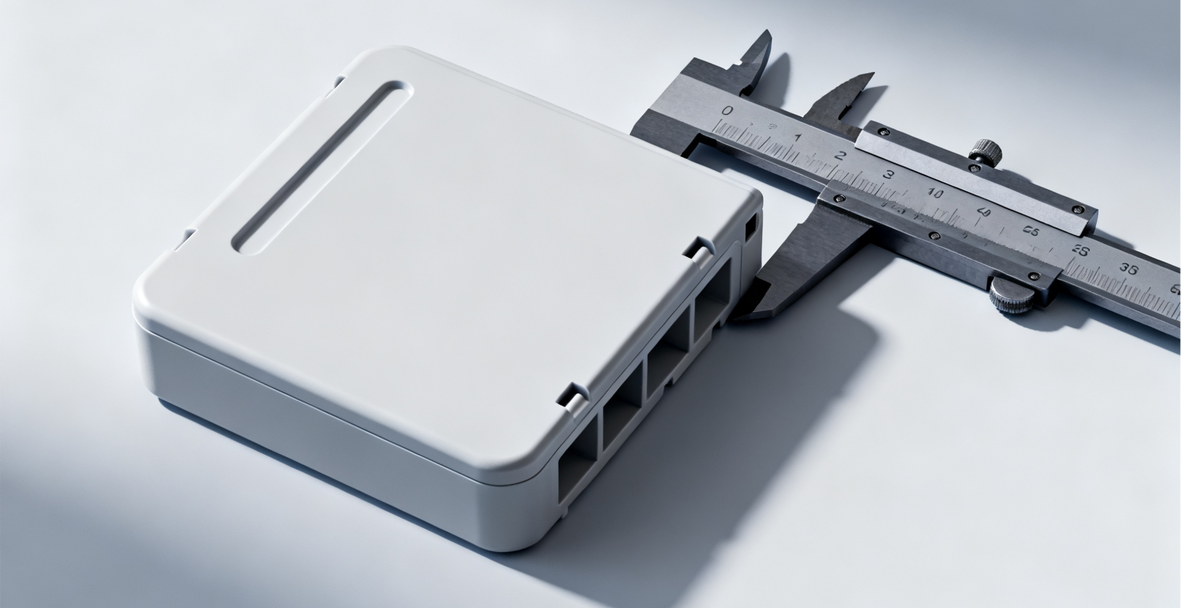
Releasing the gate arrangement with the qualified latch
Release requires an acceptable latch across the defined production and use conditions, with evidence that the selected gate and venting arrangement can reproduce it. Establish the required tests, sample traceability and changes that trigger revalidation before approving the tool revision.
Keep open issues explicit: an uncertain line through a hidden section, a trial made with another grade, incomplete conditioning or a failure mode that moved after a gate change. Each issue limits the conclusion that can be drawn from the available trial.
A cosmetic master should not override a mechanical requirement, and a strong laboratory sample should not erase a molding condition that was never recorded. The released package should connect part revision, material, tool configuration, process condition and test method to the same accepted population.
Agree how subsequent gate repairs, vent maintenance, material substitutions or cavity additions will be assessed. The goal is a controlled relationship between flow and latch performance, not preservation of one attractive simulation image. That relationship allows later changes to be evaluated against the same functional question without repeating an unfocused defect investigation.
FAQ
Can a weld line be accepted outside the visible root area?
Possibly, but its surface position alone is insufficient. Review how the line passes through the load-carrying section and how the latch is loaded during insertion and retention. A line outside the apparent root may still intersect a stressed transition or transfer region. Use representative molded-part tests under the specified conditions and document the observed failure mode. Acceptance should follow the joint's required performance rather than a fixed distance copied from another part.
Will changing to an unfilled resin solve a weak latch?
It changes the material system and may change flow, stiffness, shrinkage and allowable deformation, so it requires a broader review. A benefit at the meeting front can be offset by reduced retention stiffness or altered molded dimensions. Compare the exact candidate grades in their specified conditioning states and repeat the relevant assembly and retention checks. Treat the substitution as an engineering change with defined evidence, rather than a generic remedy for all weld-line failures.
Should weld-line samples be sectioned before testing?
Use separate, identified samples when sectioning would alter the joint's mechanical behavior. Sectioning can help locate an internal feature or investigate a fracture, but it destroys or changes the specimen intended for a functional test. Plan the sample allocation so line observation, geometry measurement and mechanical performance remain linked to the same trial conditions. Preserve untested reference parts where possible, and record the preparation method because it can influence what the section reveals.
Conclusion
Protecting a flexing root requires more than moving a visible line. Trace the complete fill path, relate the meeting region to assembly strain, and validate the resulting latch with controlled, conditioned molded-part tests. Keep line appearance, geometry and failure evidence separate enough to identify the cause of any improvement or regression.
Share the model and drawing with 6CProto for a quotation, including latch motion, mating geometry, resin grade and required insertion and retention conditions. These details make the gate and tooling review specific to the joint that must work.
{“@context”: “https://schema.org”, “@type”: “FAQPage”, “mainEntity”: [{“@type”: “Question”, “name”: “Can a weld line be accepted outside the visible root area?”, “acceptedAnswer”: {“@type”: “Answer”, “text”: “Possibly, but its surface position alone is insufficient. Review how the line passes through the load-carrying section and how the latch is loaded during insertion and retention. A line outside the apparent root may still intersect a stressed transition or transfer region. Use representative molded-part tests under the specified conditions and document the observed failure mode. Acceptance should follow the joint’s required performance rather than a fixed distance copied from another part.”}}, {“@type”: “Question”, “name”: “Will changing to an unfilled resin solve a weak latch?”, “acceptedAnswer”: {“@type”: “Answer”, “text”: “It changes the material system and may change flow, stiffness, shrinkage and allowable deformation, so it requires a broader review. A benefit at the meeting front can be offset by reduced retention stiffness or altered molded dimensions. Compare the exact candidate grades in their specified conditioning states and repeat the relevant assembly and retention checks. Treat the substitution as an engineering change with defined evidence, rather than a generic remedy for all weld-line failures.”}}, {“@type”: “Question”, “name”: “Should weld-line samples be sectioned before testing?”, “acceptedAnswer”: {“@type”: “Answer”, “text”: “Use separate, identified samples when sectioning would alter the joint’s mechanical behavior. Sectioning can help locate an internal feature or investigate a fracture, but it destroys or changes the specimen intended for a functional test. Plan the sample allocation so line observation, geometry measurement and mechanical performance remain linked to the same trial conditions. Preserve untested reference parts where possible, and record the preparation method because it can influence what the section reveals.”}}]}