

Explore Injection Molding Assembly & Process Control Guides
An overmolded grip can look complete while its rigid substrate has shifted enough to obstruct a mating feature. Inspection of the soft surface alone may miss the error, especially where the second material hides the insert. Overmolding insert movement needs a locating and measurement strategy that survives the entire second shot.
The insert must enter the mold in a known condition and remain supported as the melt arrives. Correct initial placement does not prove stability under pressure and heat. Likewise, a strong final bond does not establish the final position of the rigid component.
For a design or procurement review, distinguish locating, support and shutoff functions. A surface used to seal against flash may not be a reliable datum, and a small locator may not support a broad flexible wall. Define the finished positional requirement first, then connect it to the incoming substrate, mold contacts and trial evidence. This guide addresses movement and deformation during the second shot; the separate question of mechanical interlock strength should not replace that positional assessment.
Locate and support the insert
Identify the surfaces that locate the substrate and those that support it against the second shot. They may overlap, but their functions are different. The locating system establishes a repeatable position, while support limits deformation or movement under the process conditions.
Avient’s TPE overmolding guide describes the need to support a plastic insert against injection pressure. Its discussion is specific to the overmolding systems described; use the principle to review the actual substrate and geometry rather than assigning a universal unsupported span.
Check the incoming insert for the dimensions, warpage and local features that contact the mold. If the insert sits on a distorted surface, a nominally correct loading sequence may produce an inconsistent position. Define how the operator or automation confirms seating, and how a reversed or incomplete load is detected. Include locator access, wear and cleanliness in the tooling review. A particle trapped on a contact face can change the setup before the melt reaches the cavity.
Check that the seating confirmation observes the controlling contacts rather than only the visible loading motion. A completed robot cycle does not establish full location.
Pressure and heat induced movement
The second shot can impose both mechanical loading and a thermal event on the substrate. Evaluate the resulting movement at the relevant local feature, not only the overall outline. A thin wall may bend while the main insert remains seated, or a locally heated feature may change condition during filling.
Avient’s overmolding processing guidance treats material and temperature conditions as process specific inputs. Its published values are not a universal recipe for every TPE and substrate. Obtain the selected grades’ instructions and keep the incoming insert condition and second shot settings traceable.
Review how melt reaches the unsupported region. A gate location or filling sequence can affect the direction and timing of loading. Changing pressure alone may also affect filling and other product requirements. Test the relevant change deliberately instead of treating lower pressure as automatically acceptable. Preserve the measured finished position and any local deformation with the actual trial condition, so a visually complete overmold is not mistaken for a stable substrate.
Distinguish whole insert translation from local wall bending in the trial report, because a locator change may address one while leaving the other unchanged.
Shutoff and sealing faces
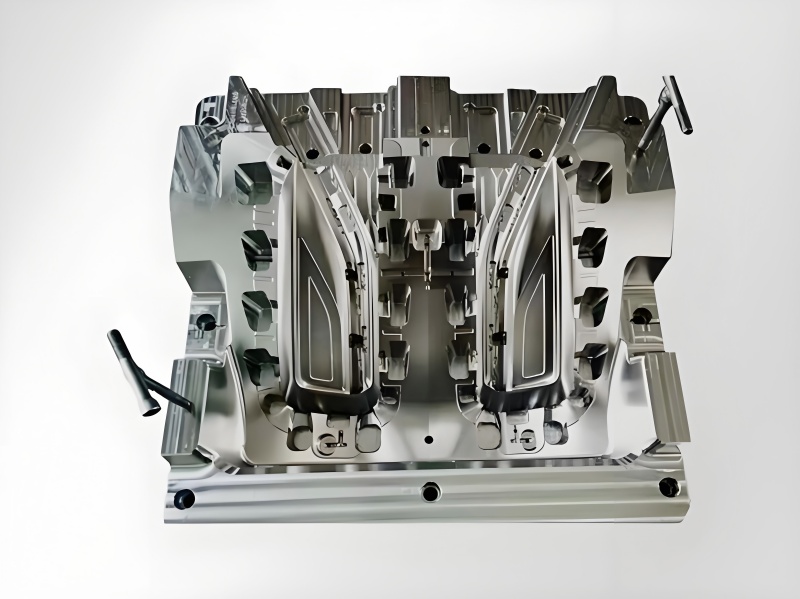
Shutoff surfaces control where the second material is allowed to flow. They need to accommodate the actual insert dimensions without damaging it or leaving an unacceptable gap. A rigid metal insert and a compliant plastic substrate do not respond identically to the same contact arrangement.
Avient’s part design guidance distinguishes shutoff behavior and tolerance accommodation. Apply the relevant material and geometry conditions; do not copy its illustrative interference dimensions into an unrelated insert. A fit that seals one substrate may crush another or prevent full seating.
Inspect the contact zones for flash, witness marks and substrate damage after the trial. If flash appears, investigate whether the insert moved, its thickness varied or the shutoff itself was unsuitable. Adding clamping force without understanding that distinction can change the failure rather than resolve it. Keep locating and sealing requirements separate on the section, and identify the permitted marks on each surface so the tool can be assessed against the actual finished appearance and function.
Preserve the flash location and insert measurements together. Reworking the boundary before recording it can remove evidence of movement at the shutoff.
Measure position in the finished part
Measure insert position relative to the final part’s functional references. The incoming substrate and finished overmold may use different accessible surfaces, so establish their relationship before the second shot hides the feature. A soft exterior should not become an accidental substitute for the required rigid datum.
Use consistent support and measurement force. Renishaw’s metrology fixturing overview describes repeatable setups, but the selected arrangement must suit a component containing both rigid and compliant materials. A fixture that compresses the overmold can change the apparent insert location without representing its service condition.
If direct measurement is impossible, agree a qualified alternative such as a defined sectioned trial or another suitable method. State its scope. A measurement at one exposed end cannot establish the position of every concealed feature. For the overmolding review, identify those hidden locations early so the manufacturing proposal includes the evidence needed to establish their final relationship.
If the final datum is concealed, define how its relation is transferred into the measurement setup and what uncertainty that transfer introduces.
Define insert position and shutoff acceptance separately
Define finished position, local deformation and shutoff acceptance as separate characteristics. The drawing should identify which references remain rigid and how the component is supported during measurement. This avoids accepting a moving insert because the outer overmold happens to look symmetrical.
| Characteristic | Reference or condition | Evidence |
|---|---|---|
| Insert position | Final functional datums | Measured relation to the required feature |
| Local substrate shape | Specified free or restrained state | Profile at critical sections |
| Shutoff result | Defined boundary and permitted witness zone | Flash and damage observations |
| Outer overmold | Defined support and contact conditions | Dimensions and cosmetic inspection |
The public scope of ASME Y14.5 supports consistent geometric communication. The actual datum and acceptance choice remain product specific. Review the measurement plan with the inspection requirements before approving tooling, especially where a compliant surface could make otherwise repeatable readings misleading.
Trace incoming inserts through controlled second-shot trials
Begin with identified incoming inserts and record their relevant dimensions before molding. Keep cavity, loading orientation, seating check and material lots connected to the sample sequence. A trial that combines different substrate conditions without traceability can hide why some parts move and others do not.
For a hypothetical hollow rigid handle receiving a soft second shot, first document the support and the required internal position. Evaluate a proposed support change with the same material and comparable molding conditions, then inspect the concealed relationship using the agreed method. The example supplies no universal pressure or temperature because those values belong to the selected materials and process.
Retain transition and restart samples when the issue appears intermittently. Record any unplanned adjustment rather than treating it as part of the intended comparison. If loading, gate position and second shot settings all change together, the trial can assess the combined route but cannot isolate each cause. State what the trial demonstrates and what the next controlled comparison must resolve.
Keep cavity identification in the report when several nests share one shot, because support or seating differences can remain local despite common machine settings.
Check rigid location beyond the visible overmold
Check the rigid insert position, soft exterior, shutoff boundaries and required function separately. A complete fill or strong bond does not establish the substrate location. Likewise, a correctly located insert can still have flash, local damage or an unacceptable exterior dimension.
Use a functional mating check only for the relationship it actually represents. A test fixture that forces the component into position may conceal the same deformation that would create difficulty in the real assembly. Identify the permitted restraint and record whether the part was conditioned before measurement.
Connect the results to the insert molding requirements and the actual finished drawing. If a critical location is hidden, preserve the trial evidence that establishes it rather than reporting only visible dimensions. Define the scope of reinspection after a locating or support change. Such a change may resolve movement while altering contact marks, flash or another feature that previously passed.
Release locating and support across incoming insert variation
Release the route when the incoming insert window, locating system, support and second shot conditions can produce the required finished relationship. Record the approved inspection setup and the changes that trigger renewed verification. A successful hand selected insert should not become the only evidence for a wider production tolerance range.
Keep unresolved DFM questions concrete: inaccessible locators, a flexible unsupported wall, variable incoming warpage or an unmeasurable hidden feature each needs a specific answer. The molding process review should connect those questions to tooling and trial scope before release.
Control repair and substitution. A different substrate grade, loading orientation or locator modification can change the result even when the overmold resin stays the same. Include tool wear and cleaning responsibilities where the seating condition matters. Production acceptance should remain tied to the finished insert location, not only to the fact that the operator completed the prescribed loading steps or that the second shot filled the visible cavity.
Define how a worn locator is detected and replaced, then verify the relevant position after replacement rather than assuming the new hardware reproduces the original setup.
FAQ
Does a strong overmold bond prove the insert did not move?
No. Bonding and position are different product characteristics. The second material can adhere while the substrate shifts or bends under the process conditions. Measure the required finished relationship from the functional references, and inspect local deformation where it matters. Keep the bonding check in its own scope. A successful adhesion result should not replace positional evidence, particularly when the overmold conceals the feature needed for the final assembly.
Can a tighter shutoff solve insert movement?
It may change how the substrate is held, but shutoff and locating functions need separate evaluation. Excess contact can damage the insert or prevent it from seating, while insufficient contact can allow flash. Review the actual substrate dimensions, compliance and support. Qualify the proposed change on representative inserts and inspect position, local damage and boundary appearance. Do not treat increased interference as a universal correction for an unstable second shot.
Should every trial use inserts at nominal dimensions?
Nominal specimens can support early setup, but production qualification needs to address the permitted incoming variation that affects seating and support. Identify the relevant dimensions and warpage condition, then select a representative trial plan. A tool that works with one hand selected insert may not accommodate the released range. Keep the incoming measurements connected to each finished result so the supported production window is based on evidence rather than assumption.
Conclusion
Control movement by connecting the incoming substrate to its final functional position. Locators establish where it starts, support helps it withstand the second shot and shutoffs define the material boundary. Each function needs its own review and finished evidence.
Use representative inserts and traceable trial conditions, then inspect the hidden and visible relationships that govern acceptance. A complete exterior and a strong bond do not establish that the rigid feature stayed where the drawing requires it. For a review with 6CProto, send the insert sections, locating surfaces and finished positional requirements for quotation. Include incoming variation and measurement access so the proposed tool can be evaluated across the intended production window.
{“@context”: “https://schema.org”, “@type”: “FAQPage”, “mainEntity”: [{“@type”: “Question”, “name”: “Does a strong overmold bond prove the insert did not move?”, “acceptedAnswer”: {“@type”: “Answer”, “text”: “No. Bonding and position are different product characteristics. The second material can adhere while the substrate shifts or bends under the process conditions. Measure the required finished relationship from the functional references, and inspect local deformation where it matters. Keep the bonding check in its own scope. A successful adhesion result should not replace positional evidence, particularly when the overmold conceals the feature needed for the final assembly.”}}, {“@type”: “Question”, “name”: “Can a tighter shutoff solve insert movement?”, “acceptedAnswer”: {“@type”: “Answer”, “text”: “It may change how the substrate is held, but shutoff and locating functions need separate evaluation. Excess contact can damage the insert or prevent it from seating, while insufficient contact can allow flash. Review the actual substrate dimensions, compliance and support. Qualify the proposed change on representative inserts and inspect position, local damage and boundary appearance. Do not treat increased interference as a universal correction for an unstable second shot.”}}, {“@type”: “Question”, “name”: “Should every trial use inserts at nominal dimensions?”, “acceptedAnswer”: {“@type”: “Answer”, “text”: “Nominal specimens can support early setup, but production qualification needs to address the permitted incoming variation that affects seating and support. Identify the relevant dimensions and warpage condition, then select a representative trial plan. A tool that works with one hand selected insert may not accommodate the released range. Keep the incoming measurements connected to each finished result so the supported production window is based on evidence rather than assumption.”}}]}