

A transferred mold can arrive intact and still be impossible to quote responsibly for production. Missing inserts, undocumented wiring, blocked cooling circuits, or an incompatible ejection interface can turn a nominally ready tool into a repair and adaptation project. The first question is what actually arrived and what the receiving shop can establish before running it.
An injection mold transfer checklist should separate tool receipt, installation compatibility, condition assessment, controlled trial, and production release. These are related decisions, but accepting a shipment of tooling does not establish that the tool will produce acceptable parts at the new location.
Preserve the distinction between the part’s approved requirements and the previous shop’s settings. The requirements remain the acceptance boundary; the settings are evidence about one machine and operating arrangement. Transferring controller numbers without understanding their meaning can create false confidence.
For a project entering low-volume manufacturing, scope the transfer assessment before treating the mold as a production-ready asset. The receiving team needs enough information to identify adaptation work, propose a trial, and explain the assumptions behind any subsequent production quotation.
What belongs in an injection mold transfer checklist inventory?
Identify the tool and every production-dependent item.
Reconcile cavities, inserts, slides, spares, drawings, wiring, cooling maps and maintenance records against the shipment, then distinguish missing items from documented changes before installation or trial planning begins.
Give each tool and replaceable insert an identifier that connects to the approved part revision. Photograph the received condition and record loose components separately. A box of apparently matching inserts is not an inventory if nobody can establish which cavity or revision each item serves.
Request the last accepted part report, cavity identification scheme, maintenance history, and known concessions. Keep ownership and permission to modify the tool clear in the commercial handover; possession alone may not resolve who can authorize repairs or design changes.
Include the ejection system in the inventory, not just cavity steel. Covestro’s ejection-design guidance shows that release and ejection are functional parts of mold design. Missing or altered components can affect the part even when the visible cavity appears undamaged. Resolve these discrepancies before relying on old sample approval.
Check machine interfaces and utility connections
Compatibility begins with the mold’s physical installation envelope and continues through nozzle, ejection, services, controls, and the intended process. A nominal clamp-force match does not demonstrate that the mold fits, opens sufficiently, or connects correctly. Obtain actual dimensions and interface details for both the mold and proposed machine.
The ARBURG technical-data library separates performance data from setup and mold-installation dimensions. That is a useful reminder to check tie-bar clearance, mold height, opening requirements, and ejection arrangements rather than selecting a press by one headline number.
Map cooling ports, flow directions, temperature-control needs, electrical connectors, heaters, thermocouples, sensors, and any pneumatic or hydraulic actions. Confirm the function and rating of each connection against the relevant equipment documentation. Do not identify wiring by connector appearance alone.
A receiving specialist should assess installation and safeguarding under the applicable procedures. The transfer checklist is an engineering coordination record, not an instruction to bypass interlocks or improvise utility adapters. Record required changes and their verification before authorizing a controlled trial.
Establish trial parts and inspection criteria
A transfer trial needs an agreed product definition and a way to identify the parts it produces. Use the current drawing, material specification, finish and appearance references, and assembly criteria. Old samples can supplement this package, but an unlabeled sample cannot establish its own revision or concession history.
Plan cavity-specific evidence where cavities or replaceable inserts can differ. Preserve part identity through conditioning and measurement so a dimensional shift can be related to its source. A mixed bag of trial parts makes diagnosis harder even if every part is nominally the same design.
Use the drawing’s datum relationships and acceptance condition. The ASME Y14.5 framework provides geometric language; the actual controlled drawing determines what the trial must demonstrate. Resolve unclear restraint, surface, or inspection requirements before the first acceptance discussion.
If the transfer follows prototype injection molding, identify which pilot approvals remain applicable. A new press, changed cooling connection, or replaced insert may require targeted verification even when the broad part design is already accepted.
Separate transfer repairs from new production pricing
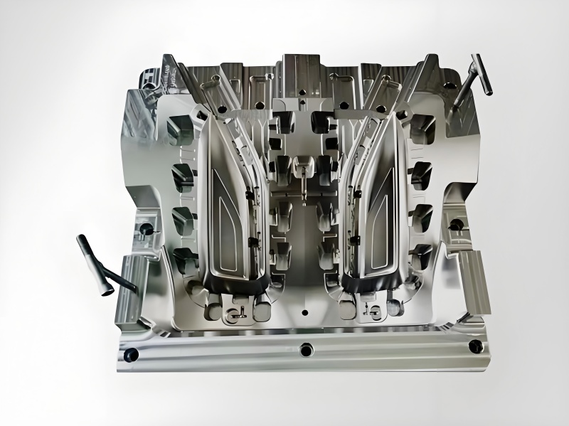
Quote the assessment and restoration of an uncertain tool separately from routine production assumptions. Receiving inspection may reveal wear, corrosion, incomplete documentation, damaged connectors, or missing spare items. These are tool-condition issues and should not disappear inside an unexplained per-part price.
Distinguish mandatory restoration, compatibility adaptation, and optional improvement. A leaking circuit is different from a proposed cycle optimization; a repair to recover the approved geometry is different from a product redesign. Assign an approval route to each category and identify who owns the resulting documentation.
DME’s mold-cooling resources include cooling maintenance as well as design and flow control. That supports checking the existing cooling system as an operating asset, rather than assuming its historical layout guarantees its current condition.
The production quotation should state the verified tool configuration and the conditions still awaiting trial. Avoid inventing a stable cycle, reject rate, or maintenance interval before evidence exists. If a commercial estimate is needed early, keep its assumptions explicit and update it when the transfer assessment resolves them.
Transfer decision-gate and evidence matrix
The transfer can proceed in stages without implying that every stage is complete. Receipt confirms identity and condition; compatibility review confirms a plausible installation; trial evidence supports a product-release decision. Keeping these gates separate helps purchasing understand why a tool can be accepted into custody yet remain unavailable for routine production.
The matrix below describes evidence boundaries. It should be adapted to the mold’s actual mechanisms and the receiving equipment, with safety-related installation decisions handled by qualified personnel.
| Gate | Required evidence | Open risk | Permitted decision |
|---|---|---|---|
| Receipt | Inventory and condition record | Missing or damaged items | Accept custody or raise discrepancy |
| Compatibility | Machine and utility interface review | Adaptation or control mismatch | Authorize installation work |
| Tool readiness | Repair and function checks | Unstable mechanisms or cooling | Authorize controlled trial |
| Part trial | Traceable cavity-specific results | Product conformity and stability | Release defined production scope |
Do not use the table as a substitute for an installation procedure. Its purpose is to make the technical and commercial release conditions visible to everyone approving the transfer.
Worked transfer assessment scope
Assume an illustrative two-cavity enclosure mold arrives with its latest part drawing, one retained sample, and an incomplete cooling map. One connector has been replaced, and the spare insert package lacks revision labels. These are assumed conditions for scoping, not an account of a customer transfer.
The first work package is inventory reconciliation and documentation recovery. Identify the connector’s actual function and rating, verify the spare inserts against tool records, and trace the cooling circuits. Do not begin by copying a previous machine’s settings into the receiving controller.
Next establish the trial population and inspection plan for both cavities. Record cooling conditions and part identity so a cavity-specific dimensional or appearance issue is not averaged away. DME’s cooling-flow monitoring information describes the relevance of flow and thermal-transfer behavior; it does not guarantee that an old circuit is clear merely because fluid exits a port.
The resulting quotation can separate documented repairs, required adaptations, the controlled trial, and production after approval. This gives procurement concrete scope boundaries without fabricating prices or treating uncertainty as an established manufacturing condition.
Acceptance records and limits of transferred evidence
Retain a before-and-after record for repairs, insert changes, and interface adaptations. Each record should identify the tool configuration it describes and the part revision it is intended to produce. Historical reports remain useful evidence, but only when their relationship to the transferred hardware is known.
Evaluate the comparability of measurements from the old and new locations. A difference may reflect the part, the process, or the measurement setup. NIST’s uncertainty-analysis framework supports assessing whether the available result is suitable for the acceptance decision instead of treating all reported decimal places as equal evidence.
Document the transferred process information in terms the receiving team can interpret. Controller settings can depend on machine architecture, units, response, and the way values are displayed. Preserve the intent and observed outcome, not just screenshots of numbers.
Close each trial issue with a disposition and the evidence that supports it. If only a limited run or selected cavity is approved, state that boundary. An approval for one documented condition should not become an assumption that every recovered insert or future repair is automatically covered.
Release and handover checklist for the receiving shop
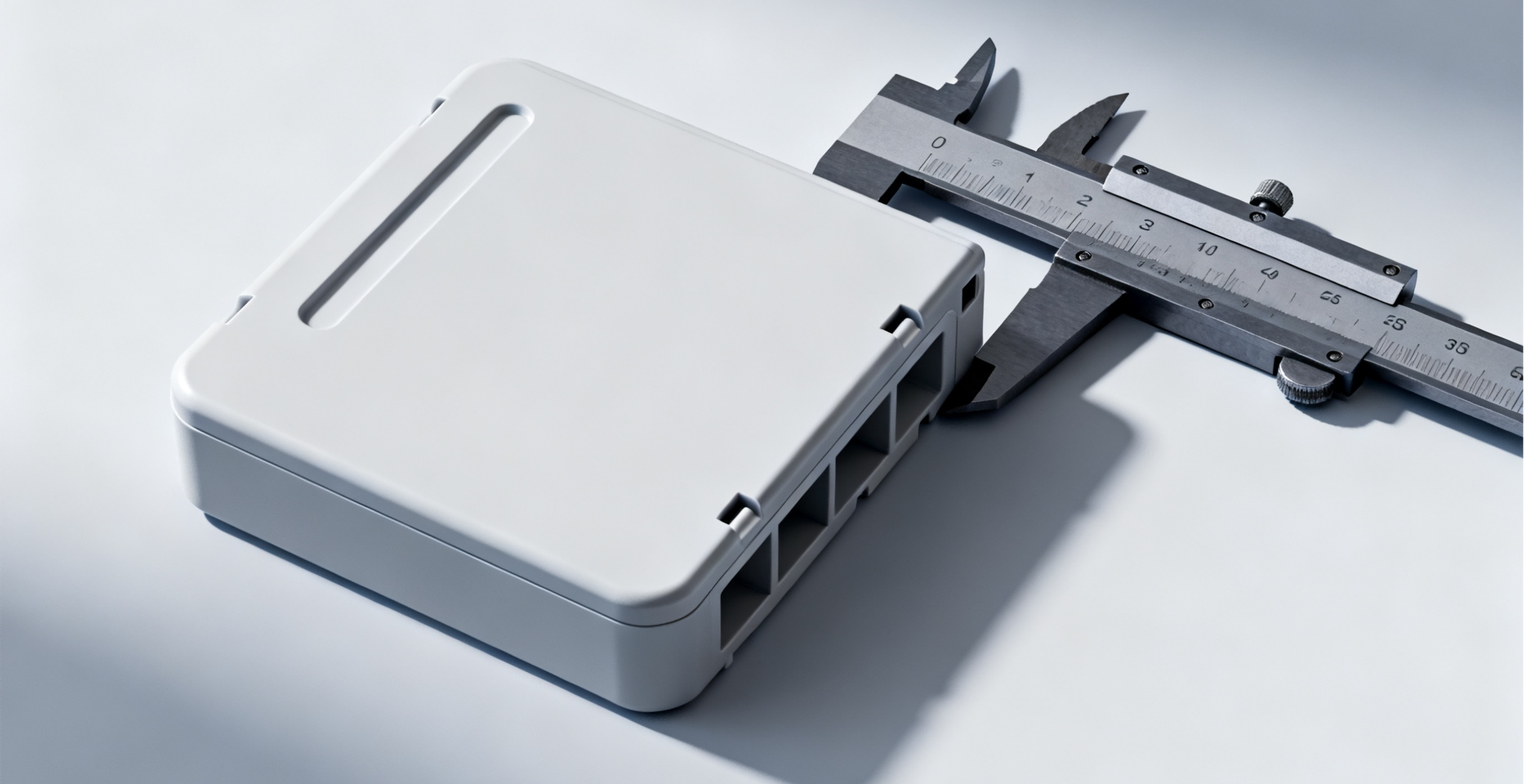
The final handover should allow the receiving team to run, inspect, maintain, and identify the approved tool configuration. Include the reconciled inventory, updated interface maps, repair records, current part definition, trial reports, and the rules for changing replaceable items. Keep obsolete configurations as history, clearly separated from production instructions.
Preserve the process inputs whose changes could alter approved characteristics. Autodesk’s warpage discussion identifies cooling, orientation, and material effects, making those inputs relevant to transfer review rather than incidental setup details. The receiving process should be supported by its own observed evidence.
For any remaining development work, the rapid-prototyping workflow can be scoped as a separate activity instead of being hidden in a production release. This is particularly useful when a replacement insert changes the product interface.
Identify maintenance triggers and the evidence needed after future repairs. Tool transfer is complete when ownership, configuration, operating interfaces, and product acceptance are understandable together, not merely when the mold has reached the new shop floor.
FAQ
Can the receiving shop rely on the previous shop's approved samples?
The samples can help establish appearance or diagnose a difference, but they need identity, revision, condition, and a clear relationship to the acceptance specification. They do not independently prove that the transferred mold is unchanged or that the receiving process will reproduce them. Use them alongside controlled drawings and traceable trial data. If a retained sample reflects a temporary concession, preserve that information so the concession is not mistaken for a permanent product requirement.
What if the mold's CAD and maintenance records are missing?
Start with a documented condition and inventory assessment, then define the information that must be recovered or recreated before installation, repair, or production can be approved. The necessary scope depends on the mechanisms, interfaces, and part requirements. Avoid promising a routine production transfer before this assessment. Any reconstructed drawing should be identified as such and checked against the actual tool; an old part model alone does not describe cooling, ejection, wiring, or replaceable tooling.
Should a transfer include every historical process setting?
Retain useful history, but organize it around the configuration and outcome it describes. A setting without units, machine identity, material condition, or an associated trial result can be misleading. Separate proven operating records from abandoned experiments and temporary workarounds. The receiving team should establish its own appropriate process using qualified setup procedures and product evidence. Historical settings are a starting reference, not an automatic authorization to run an incompatible machine or utility arrangement.
Conclusion
A sound mold transfer establishes what the receiving shop has, what it can connect and operate, and what evidence can release the resulting parts. Inventory, interfaces, tool condition, and product acceptance belong in one coordinated record, with separate gates for custody, trial, and routine production.
This separation also improves the quotation. Repairs recover or restore a tool; adaptations make it compatible; a controlled trial establishes the new operating evidence. None should be hidden inside an unsupported production assumption. The final package should preserve cavity identity, approved revisions, and the checks required after future maintenance or insert replacement.
6CProto’s molding and project-management scope can support a discussion of tool-transfer requirements. To define an assessment, send the tool inventory, part drawing, mold interfaces, maintenance history, and last accepted reports for quotation. Identify missing records and known defects so the initial scope reflects the actual condition of the transferred asset.
{“@context”: “https://schema.org”, “@type”: “FAQPage”, “mainEntity”: [{“@type”: “Question”, “name”: “Can the receiving shop rely on the previous shop’s approved samples?”, “acceptedAnswer”: {“@type”: “Answer”, “text”: “The samples can help establish appearance or diagnose a difference, but they need identity, revision, condition, and a clear relationship to the acceptance specification. They do not independently prove that the transferred mold is unchanged or that the receiving process will reproduce them. Use them alongside controlled drawings and traceable trial data. If a retained sample reflects a temporary concession, preserve that information so the concession is not mistaken for a permanent product requirement.”}}, {“@type”: “Question”, “name”: “What if the mold’s CAD and maintenance records are missing?”, “acceptedAnswer”: {“@type”: “Answer”, “text”: “Start with a documented condition and inventory assessment, then define the information that must be recovered or recreated before installation, repair, or production can be approved. The necessary scope depends on the mechanisms, interfaces, and part requirements. Avoid promising a routine production transfer before this assessment. Any reconstructed drawing should be identified as such and checked against the actual tool; an old part model alone does not describe cooling, ejection, wiring, or replaceable tooling.”}}, {“@type”: “Question”, “name”: “Should a transfer include every historical process setting?”, “acceptedAnswer”: {“@type”: “Answer”, “text”: “Retain useful history, but organize it around the configuration and outcome it describes. A setting without units, machine identity, material condition, or an associated trial result can be misleading. Separate proven operating records from abandoned experiments and temporary workarounds. The receiving team should establish its own appropriate process using qualified setup procedures and product evidence. Historical settings are a starting reference, not an automatic authorization to run an incompatible machine or utility arrangement.”}}]}