

Explore Injection Molding Assembly & Process Control Guides
A small prototype correction can commit a mold to a shape that cannot be reversed by another simple cut. The important decision is not the size of the CAD edit, but which tool surfaces must change and whether the existing construction can accommodate them. Prototype mold engineering changes need that local geometry review before machining begins.
Separate the requested product result from the proposed tool modification. Increasing a plastic rib, reducing a hole or moving a shutoff can involve different tool elements even when each change appears minor on the part model. A replaceable insert may preserve options, but only if its boundary, support and access suit the revised feature.
Map each CAD edit to the cavity, core, shutoff or insert surface that must change. Mark whether the requested result requires metal removal, metal addition or replacement of a tool element. For each change, preserve the baseline, identify the affected steel and define the next trial’s evidence. That makes the authorization a concrete manufacturing decision rather than a general instruction to make the part fit.
Separate reversible and irreversible changes
Classify the change by what happens to the tool. Removing material can enlarge a plastic volume in a simple cavity region; reducing that plastic volume can require added tool material or replacement. The direction depends on the actual core, cavity and movable elements, so inspect the tool section rather than relying on the part’s outside appearance.
Protolabs’ metal safe design explanation describes the basic asymmetry between removing and adding mold material in its rapid tooling system. Use that mechanism to frame the review, while recognizing that repair and replacement options depend on the actual tool construction and approved process.
A reversible product decision is not necessarily a reversible tool operation. Retain the previous insert or baseline geometry when practical and identify what restoration would require. If welding or another repair is proposed, treat it as a separate manufacturing proposal with its own risks and verification. Do not describe material removal as reversible simply because the CAD file can return to an earlier revision.
Identify the physical surface in the authorization, including which tool half or element contains it, so the same product edit is not interpreted in opposite directions.
Steel safe dimensions and stock
A steel safe allowance reserves material for a likely direction of later adjustment. It is a deliberate geometric condition, not an unspecified promise that any dimension can be corrected. Show the controlling tool surface and the intended product change so the reserved stock remains meaningful.
For a hypothetical rib, the team may begin with less plastic and retain the option to remove tool material to enlarge it. That option still depends on neighboring walls, local strength and machining access. State the initial and proposed dimensions as controlled revisions rather than adding an informal allowance to a released nominal.
Check remaining stock around cooling passages, ejectors, screws and insert boundaries. A local cut can consume material needed for another tool function. The Protolabs modification discussion also identifies constraints involving parting lines and other construction features. Its process limits are specific to its service; the useful review principle is that a metal safe direction alone does not establish feasibility of every surrounding tool element.
Measure the existing tool condition before calculating available stock. The nominal original model may no longer describe a surface that has already been reworked.
Insert boundaries and access
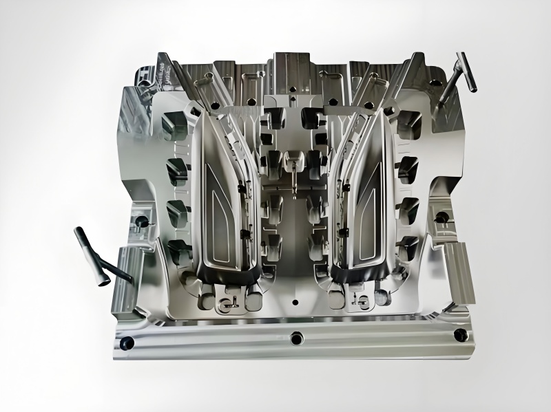
A replaceable insert is useful when its construction isolates the likely change without compromising support, sealing or thermal behavior. Its boundary should be chosen from the tool and part functions, not merely around the edited region in CAD. A new insert must still locate consistently and preserve the adjoining cavity surfaces.
Avient’s mold design guidance discusses tool materials and the use of inserts in the systems it covers. That context supports reviewing the element as part of the mold, rather than a detached block. Check fasteners, backing, cooling access and the ability to machine and inspect the revised surfaces.
Identify any witness line, shutoff or vent affected by the boundary. A replaceable element that crosses a cosmetic or sealing zone can create another acceptance question. If a local feature changes repeatedly, compare replacement with cumulative rework of the original element. Keep each installed insert traceable so a trial sample can be related to the tool geometry that actually produced it.
Include the adjoining fit in the replacement inspection, because a correct cavity surface can still sit incorrectly when the insert is installed in its pocket.
Document the next trial and verification scope
Before cutting, define what the next molded trial must demonstrate. Identify the revised feature, the unchanged references and the product characteristics that could be affected indirectly. The machining inspection establishes the tool change; molded parts establish the resulting product under the tested process.
Record the baseline tool and part revision, proposed modification, resin grade, relevant process condition and planned sample identification. If the material also changes, separate that variable or state that the trial qualifies a combined change. Otherwise a dimensional improvement may be attributed to the wrong cause.
Plan access for measurement before the tool returns to molding. Renishaw’s metrology fixturing information describes repeatable support and reference setups. For this review, preserve the locating chain between the old tool measurement, revised element and molded part report. A change measured from a convenient new surface can obscure whether the intended functional relation moved or the inspection reference changed instead.
Keep a baseline molded sample with the original tool identity and measurements so the next trial can be compared with a traceable physical condition.
Link each tool modification to a molded-part acceptance check
Use an acceptance table that links the requested part change to the affected tool and the evidence after molding. Include nearby characteristics when the modification can influence their function. Avoid approving the whole tool with a single revised dimension.
| Change item | Tool question | Trial evidence |
|---|---|---|
| Rib or wall adjustment | Removal direction and remaining stock | Local size and resulting part behavior |
| Hole or boss revision | Core or cavity element affected | Feature size and location from datums |
| Insert replacement | Location, support and boundary continuity | Adjoining geometry and witness condition |
| Shutoff change | Contact and venting consequences | Flash and permitted edge condition |
Use the public scope of ASME Y14.5 for consistent geometric communication, with application specific limits on the released drawing. Link the resulting report to the inspection requirements rather than an informal marked up screenshot.
Compare a direct cavity cut with a replacement insert trial
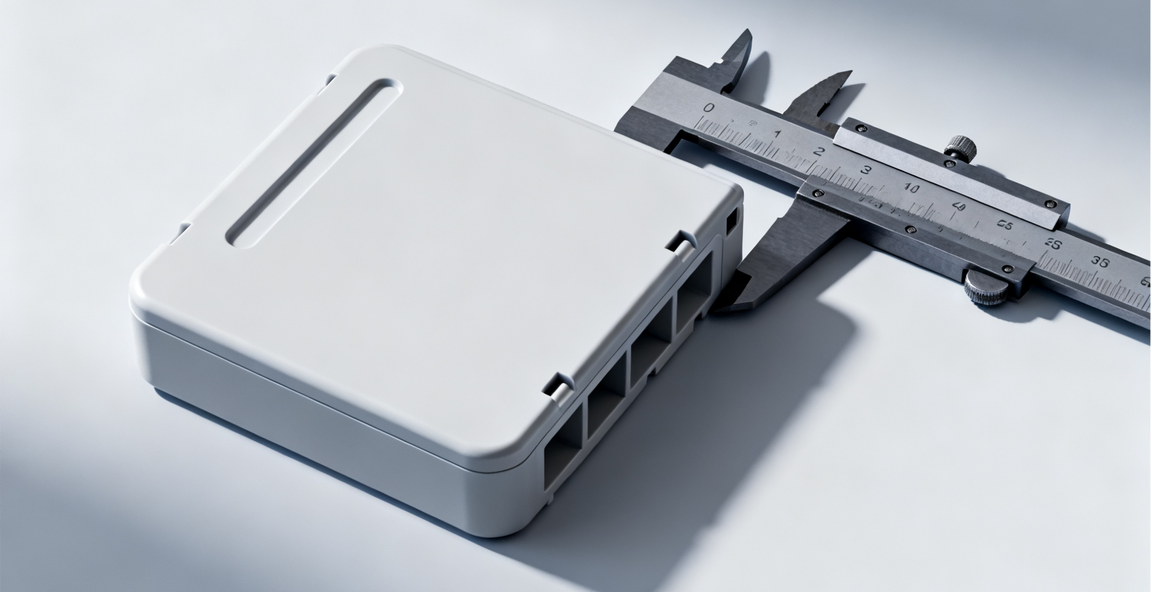
For a hypothetical enclosure revision, suppose a latch rib must increase while a nearby sealing edge must remain unchanged. First section the relevant tool region and confirm which cut creates the desired additional plastic. Check whether it affects the shutoff, ejector clearance or an insert boundary.
Compare a direct cut with a replacement element on the actual construction. Record what can be restored, what material remains and how each option will be inspected. The comparison should include the next trial, not only machining cost. A cheaper cut can become expensive if it consumes the only remaining adjustment route before the functional result is known.
Keep trial samples identified by installed tool element and revision. For prototype molding, use the intended resin and a documented process condition, then evaluate the changed latch and nearby seal. The example is a decision sequence, not a claim that the two functions will respond independently to a local tool modification.
If direct machining consumes the last adjustment stock, identify that consequence before approval and compare the replacement option while both routes remain available.
Inspect the revised feature and its affected neighbors
Inspect dimensions, appearance and function after the revised molding trial. A machined cavity can match its new model while the molded part still fails fit, ejection or another requirement. Keep the product result separate from confirmation that the toolmaker executed the cut correctly.
Check the changed region and the affected neighbors identified before machining. If a new witness line or flash appears, preserve the location and sample history before reworking the surface again. Repeated undocumented corrections can make it impossible to tell which installed condition produced the passing part.
Connect the findings to the tooling revision review. State whether the trial demonstrates the requested improvement, reveals a new issue or needs another controlled iteration. A successful hand modified sample is not evidence that the mold itself produces the feature. If any sample was trimmed, polished or adjusted, retain that fact in the sample traceability and verify the actual production route separately.
Authorize the cut with remaining stock and restoration understood
Authorize the cut or insert replacement only after the requested geometry, affected construction and next trial scope are clear. Keep the before and after models, tool element identity and approved repair route together. The authorization should state what is permitted, not simply approve a general concept of improving fit.
Resolve remaining stock, tool access and inspection limitations before removing material. The molding process review should also identify changes affecting gates, vents, cooling, ejectors and material behavior where relevant. A local drawing edit can cross one of those interfaces without making it visually obvious.
Release the new revision when the required product evidence passes and the installed tool condition is documented. Retain superseded elements where the agreed project controls require them. A replacement insert preserves a route back only if its location and supporting construction remain compatible; the word replaceable should not carry a promise that every future design change fits the same mold.
Record which previous evidence remains applicable and which characteristics need retesting; a local change does not justify either blanket approval or an undefined full restart.
FAQ
Is every steel safe change inexpensive?
No. Material removal direction is only one factor. Access, remaining stock, cooling, shutoffs, ejectors and inspection can determine whether a local change is practical. Evaluate the actual tool section and the next molding trial before comparing cost. A small part edit can affect a much larger tool interface. Ask for the machining proposal and verification scope together so the quotation covers the accepted product result rather than only a nominal cut.
Does replacing an insert avoid another molding trial?
It changes the tool element, so the relevant product characteristics still need verification. The insert must locate correctly, preserve adjoining surfaces and produce the intended part under the selected molding condition. Inspect the element before installation and evaluate the affected dimensions, appearance and function after molding. A previously passing design elsewhere in the tool does not establish that the replacement interface or revised local feature is acceptable.
Can a resin change be evaluated during the same tool modification?
It can be assessed as a combined change when the trial is designed that way, but the result may not isolate the effect of each variable. Resin behavior can influence dimensions and processing, so retain both material and tool revision information with the samples. If the goal is to understand a specific local correction, separate the changes where practical. Do not attribute every improved dimension to the cut when the material also changed.
Conclusion
Choose between cutting and replacement from the local tool construction and the evidence needed next. A metal safe direction can preserve an adjustment option, but remaining stock, access and neighboring tool functions still determine whether it is usable. Keep reversibility tied to physical elements rather than the ease of reverting a CAD file.
Define the trial before authorizing material removal, then inspect the changed product and its affected neighbors. For a review with 6CProto, send the current tool section, proposed part revision and trial acceptance scope for quotation. That package makes the change reviewable and helps avoid consuming the remaining adjustment route before the functional result has been established.
{“@context”: “https://schema.org”, “@type”: “FAQPage”, “mainEntity”: [{“@type”: “Question”, “name”: “Is every steel safe change inexpensive?”, “acceptedAnswer”: {“@type”: “Answer”, “text”: “No. Material removal direction is only one factor. Access, remaining stock, cooling, shutoffs, ejectors and inspection can determine whether a local change is practical. Evaluate the actual tool section and the next molding trial before comparing cost. A small part edit can affect a much larger tool interface. Ask for the machining proposal and verification scope together so the quotation covers the accepted product result rather than only a nominal cut.”}}, {“@type”: “Question”, “name”: “Does replacing an insert avoid another molding trial?”, “acceptedAnswer”: {“@type”: “Answer”, “text”: “It changes the tool element, so the relevant product characteristics still need verification. The insert must locate correctly, preserve adjoining surfaces and produce the intended part under the selected molding condition. Inspect the element before installation and evaluate the affected dimensions, appearance and function after molding. A previously passing design elsewhere in the tool does not establish that the replacement interface or revised local feature is acceptable.”}}, {“@type”: “Question”, “name”: “Can a resin change be evaluated during the same tool modification?”, “acceptedAnswer”: {“@type”: “Answer”, “text”: “It can be assessed as a combined change when the trial is designed that way, but the result may not isolate the effect of each variable. Resin behavior can influence dimensions and processing, so retain both material and tool revision information with the samples. If the goal is to understand a specific local correction, separate the changes where practical. Do not attribute every improved dimension to the cut when the material also changed.”}}]}