

Explore Injection Molding Assembly & Process Control Guides
A precisely machined insert can still finish in the wrong place. Its own diameter tolerance does not control how the mold locates it, how the cavity fills around it, or how the molded part is inspected. For insert molding design, the first purchasing question should be which surfaces establish the final assembly location.
Why insert location belongs on the drawing early
Insert molding design should define the insert’s final position from functional part datums before tooling starts. Identify locating surfaces, orientation, exposed metal, and protected threads. Review how the mold will support and seal around the insert, then verify position after molding rather than assuming an accurate loose insert guarantees an accurate assembly.
Buyer question: can the toolmaker infer the location from the CAD? Nominal geometry shows the intended arrangement, but it does not establish allowable variation or the inspection reference. Identify the assembly interfaces that matter and apply a consistent drawing convention. ASME Y14.5 provides the language for stating and interpreting geometric requirements.
The insert molding review should connect those requirements to the proposed supports. Ask which insert feature seats against the tool and whether normal variation in that feature changes the final position. Keep the locating concept visible in the DFM response.
Retention features that survive ejection
Buyer question: are knurls enough to approve retention? They are one geometric input, not a complete acceptance result. Distinguish resistance to rotation, axial extraction, and the loads introduced during ejection. A feature that resists an assembly screw can still be poorly supported while the part leaves the mold.
SPIROL’s insert catalog discusses molded-in insert features, plastic engagement, and core-pin fit. Use the selected insert’s design guidance rather than copying a post-installation hole recommendation into a molded-in design.
Review how the surrounding plastic fills the retention features and whether thin ligaments or weld regions become the weak path. Ask the toolmaker to show the ejection contact areas and release direction. Specify a representative torque or pull-out test only after identifying the application load and required failure criteria. The catalog’s general design rationale does not establish the finished part’s allowable load.
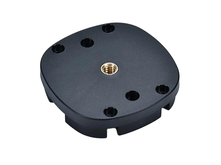
Preheat and contamination risks
Buyer question: should every metal insert be preheated? No universal setting applies across resins and insert geometries. Select any preheat requirement from the polymer supplier’s guidance and confirm that the loading method can maintain the intended condition. A loosely stated warm insert requirement is difficult to reproduce across shifts.
The Amodel PPA processing guide discusses insert holding and circumstances where preheating large metal inserts may help. Its recommendations belong to that material context. They are not evidence for a common temperature for all insert molding jobs.
Specify the incoming surface condition as well. Oils, corrosion protection, loose particles, or unapproved cleaning residues can change the local interface or create contamination. Record any coating that must remain on the insert, and agree a cleaning method compatible with it. Packaging and handling should preserve that approved state until loading.
Flash paths around inserts
Buyer question: why does a thread need protection if the insert is already threaded? Melt can enter an opening or pass along a clearance unless the tooling provides an effective barrier. The DFM review must identify the sealing surface and its tolerance, not merely add a note requiring clean threads.
For a selected molded-in threaded insert, a core pin or another locating feature may also participate in thread protection. A blind-ended design can provide a different barrier, subject to the selected component’s guidance. Confirm that insertion force, seating, and mold closure will not damage the feature used for sealing.
The BASF Ultraform brochure addresses metal insert preparation and mold parting surfaces in its POM processing discussion. The broader DFM lesson is to review surface condition, anchoring, and sealing together. Specify whether flash is prohibited on functional metal and how any permitted trimming will be checked without damaging it.
Table: insert materials and common pitfalls
Buyer question: which insert material makes the design easiest? Begin with the function and then assess manufacturing risks. Conductivity, corrosion exposure, strength, coating, and the polymer’s thermal cycle can matter more than the insert’s purchase price. Material identity also determines what incoming evidence the supplier needs.
SPIROL’s insert range distinguishes installation styles, including molded-in and post-mold options. Installation method should be part of the component designation so that a visually similar replacement does not change the manufacturing assumption.
| Insert category | Potential concern | Drawing or purchase control | Check after molding |
|---|---|---|---|
| Brass threaded insert | Rotation, axial retention, obstructed thread | Exact component and exposed thread requirements | Position, thread access, agreed retention trial |
| Steel pin or bushing | Corrosion protection and support geometry | Material, coating, locating diameters | Alignment and exposed-surface condition |
| Electrical contact | Orientation and protected contact surfaces | Contact datum and prohibited molding areas | Position and required electrical checks |
| Thin metal stamping | Distortion or inconsistent seating | Flatness, locating features, handling condition | Final geometry and functional clearance |
Inspection of insert position after mold
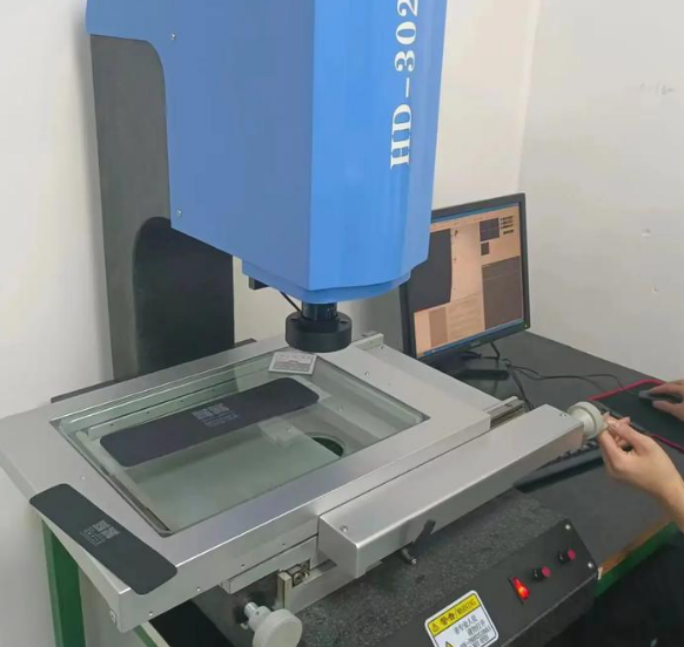
Buyer question: can incoming insert inspection replace final position inspection? It cannot show what happened during loading, filling, cooling, and ejection. Measure the final relationship between the metal feature and the plastic part’s functional datums, using a support arrangement that does not artificially straighten the component.
Define the measurement method before samples arrive. An exposed bore may permit direct inspection, while an encapsulated feature may require a justified indirect method or a destructive development check. Do not infer hidden metal position from an external plastic surface unless that relationship has been established.
Use the standards and tolerances reference to start the discussion, then place project-specific limits on the controlled drawing. Keep tool cavity, insert lot, and molding sequence traceable in sample records. If a position fails, these identifiers help distinguish component variation from a particular loading or cavity condition.
When to prototype insert molding first
Buyer question: when is a prototype trial worth the extra work? Prioritize it when the locating arrangement is uncertain, the insert is difficult to support, or the functional consequence of movement is substantial. The useful trial reproduces the relevant loading and molding constraints, not just the outside appearance.
Review the plastic injection molding scope with the insert drawing and a marked cross-section. First agree the seating and protected areas; next approve a trial plan; then inspect final insert position and the critical functional characteristic. Record any development modification before authorizing the next batch.
A hand-assembled mock-up can reveal access and orientation problems, but it does not validate melt pressure, local cooling, or ejection. Identify which questions remain open after the mock-up. Prototype approval should close those questions with appropriate evidence rather than become a broad authorization based only on a part that looks correct.
FAQ
These questions address specification details that should be settled before sample approval.
Who should approve a substitute insert from another supplier?
The owner of the controlled component specification should evaluate it with the molding and product teams. Matching thread size does not establish matching locating dimensions, knurls, coatings, or sealing surfaces. Compare the complete component definition and assess the need for a molding trial. Keep the substitution approval linked to its supplier and revision so that an accepted alternative does not become an uncontrolled generic replacement.
Should retention testing destroy every production part?
The inspection plan should distinguish development testing, routine process checks, and shipment acceptance. A destructive trial may be useful for validating a particular interface, but applying it to every delivered part would consume the product. Agree the sample basis and acceptance response according to risk and available process evidence. The test method must represent the required load rather than an arbitrary attempt to break the part.
Can molded flash be removed from a thread after the fact?
That depends on the permitted repair process and the thread acceptance requirements. Cleaning or chasing can damage the thread or change a protected surface, and a visually clean opening may still contain debris. Agree any repair method before use, then inspect the affected feature. Repeated repair should also trigger a review of the tooling barrier and incoming insert variation.
Send the insert drawing, assembly CAD, and protected-surface requirements to 6CProto for a quote and DFM review. Ask the response to show the locating concept and final inspection plan before tooling release.