

Explore Injection Molding Assembly & Process Control Guides
A drawing that calls for a 1.2 mm clear wall does not prove the moulded lighting face is 1.2 mm where light actually passes. Local packing, core deflection and cooling imbalance move thickness toward the gate or starve the last-to-fill zone, and the light box notices before the caliper does. Buyers who require disciplined wall thickness measurement injection molded lighting parts catch transmittance and sink risk while steel can still be corrected.
This page owns how and when to measure: why nominal wall is not enough, sectioned samples versus non-destructive gauges, where to sample relative to gate and last-to-fill, acceptance criteria tied to light transmittance, and which records belong with first article. The hub lists thickness checks among order documents; the methods and sampling logic live here. Application context links to the bespoke pendant light programme.
Why is nominal wall on the drawing not enough?
Moulded walls vary; light follows the real section.
Injection moulding rarely delivers a perfectly uniform thin wall. Gate-proximal zones can pack thicker; far edges can run thin; cores can deflect under pressure and open or close the section. On opaque parts a tenth of a millimetre may sit inside tolerance with no cosmetic drama. On translucent lighting parts that same variation changes optical path length and cooling rate, producing haze bands or bright spots.
Relying only on a CAD nominal therefore misses the property the customer sees. Thickness control is both a dimensional and an optical control. Call out measurement locations on the same face that the light-box evaluates, and state whether thickness applies as-moulded or after any secondary polish that removes material.
General measurement practice guidance from NIST MEP and drawing clarity expectations under ASME Y14.5 still apply: define datums, methods and accept/reject rules. Polymer processing context from Plastics Europe and the Plastics Industry Association explains why viscosity and packing drive local thickness; your FAIR must still show numbers on the real part. 6CProto treats thickness maps as part of free DFM follow-through on injection molding programmes from Zhongshan and Guangdong partners.
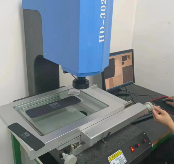
When should you use sectioned samples versus non-destructive gauges?
Section for absolute truth; gauge for lot trending.
A carefully sectioned and polished sample shows the true wall at chosen cuts, including sinks toward the core and any voids. It destroys the part and takes time, so it suits tool prove-out, material changes and disputed lots. Ultrasonic or other non-destructive thickness gauges support incoming and in-process checks without scrapping every piece, provided the instrument is calibrated on the same clear grade and curvature.
Do not mix methods silently. If T1 used sections and production uses ultrasonics, correlate both on the same pieces before freezing the control plan. Curved pendant-style faces need probe fixtures or section planes defined on the drawing; freehand ultrasonic readings on a compound curve create false drift.
Optical grades complicate ultrasonic coupling and velocity assumptions. Build a grade-specific calibration coupon with known micrometer thickness. Machine builders and process references from firms such as ARBURG and ENGEL discuss process monitoring; they do not replace your thickness correlation study.
Where should you sample relative to gate and last-to-fill?
Measure gate-near, mid-flow and last-to-fill zones.
A single centre reading can pass while the rim that carries the brightest LED ring runs thin. Sample at least three logical zones on each critical lit face: near the gate, at mid-flow, and at the predicted last-to-fill or weld region. Add points at local features that change section — logos, lens steps, or rib roots behind the face — because those are where sinks and thick spots hide.
Align sampling with the gate map from tooling DFM. If gates move after T1, rebuild the thickness map; old points may no longer represent risk. For multi-cavity tools, sample cavities that historically run short or cold rather than only cavity one.
Sink-mark physics at thick-to-thin transitions is covered in the shop’s sink marks in injection molding guide. Use that page when a thick boss behind a thin lit face is the root cause; keep this article on measurement strategy rather than re-teaching rib ratios.
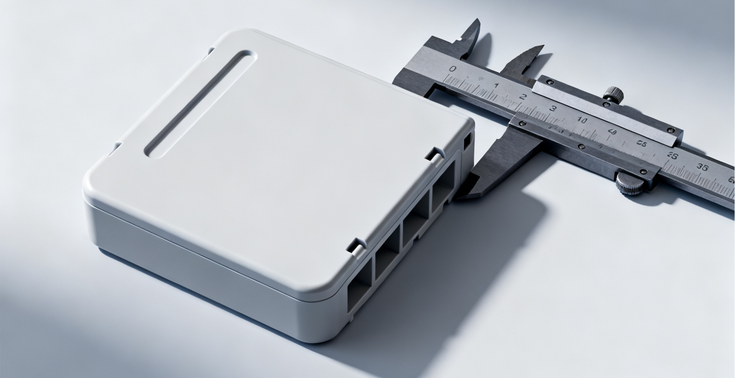
How should acceptance criteria tie to light transmittance?
Couple thickness bands to the light-box standard.
A thickness tolerance that ignores optics can accept parts that look uneven when lit. Write dual criteria where needed: a dimensional band for structural integrity and an optical acceptance under a defined source. Some programmes allow a wider dimensional band if the light-box passes; others tighten thickness because transmittance is specified as a measured value on production pieces.
Photograph limit samples at the same camera distance and exposure. Store them with the FAIR so later lots are not judged by memory. If colour or diffuser tint changes, re-establish limit samples; pigment scattering changes how thickness variation reads.
Material optical datasheets from producers such as Covestro and Röhm report neat-resin transmittance on plaques. They do not certify your moulded wall map. Prototype tools via prototype injection molding are useful for proving measurement methods before production steel.
What records belong with first article?
Map, method, correlation and light-box photos.
First-article packages for thin lighting walls should include: the thickness map with point IDs; instrument identity and calibration reference; section photos if destructive methods were used; ultrasonic correlation data; process settings for the shots measured; and light-box images of the same pieces. Without that bundle, a later thin-lot debate becomes opinion.
Maintenance records matter once the tool runs. Core wear and cooling fouling change thickness over time. Tie periodic thickness audits to shot count or calendar, especially on high-shear optical gates that also wear. Broader mould durability notes live on the custom mould design page.
Ask for these records in the RFQ line items, not as a surprise after T1. Hot-runner documentation from suppliers such as Mold-Masters and tool standards from HASCO help identify hardware revisions that should trigger re-measurement.
Operator training closes the loop. A mapped point list is useless if each inspector picks a slightly different spot on a glossy curve. Provide fixture nests or printed overlays for ultrasonic probes, and require two-person verification on the first piece of each shift when the part is appearance-critical. Digital photos of probe placement beside the numeric sheet prevent arguments months later.
Process alarms should reference thickness risk, not only fill time. A gradual rise in pack pressure that keeps dimensions inside a wide band can still thin the last-to-fill optic. Tie SPC on key thickness points to the same shots used for cosmetic audits so engineering sees coupled drift. When quoting alternate moulders, require them to run your map on first article so results stay comparable across suppliers.
Incoming inspection should not invent a thinner protocol than first article. If FAIR used nine mapped points and a light-box photo set, receiving cannot collapse that to one micrometer hit on a convenient flange. Write the reduced skip-lot rules explicitly when process capability is proven, including which points remain mandatory on every lot for optical parts.
Core and cavity temperature logs belong beside thickness charts when diagnosing drift. A cooling circuit that fouls slowly thins one zone while the press recipe looks unchanged. Pairing thickness SPC with circuit flow or temperature checks shortens root-cause time on translucent lighting tools.
Design changes that add logos, capacitive touch windows or decorative steps reopen the map even when overall envelope thickness is unchanged. Treat those ECO items as thickness-risk events equal to a gate move. Industrial design and quality should sign the revised point list before steel polishing begins.
For overseas dual-source strategies, ship the same calibrated reference coupons and photo standards to each moulder. Without shared artefacts, each plant’s ultrasonic velocity table and lighting booth create incompatible accept/reject calls on identical geometry.
Finally, store thickness data in the same PLM or quality system as the tool revision, not only in email attachments. When a cavity is welded or a core is replaced years later, engineers need the original map to know what “back to T1” means for a lit face.
Buyers should also state whether warped parts may be restrained in a fixture during thickness checks. Restraining a bowed clear panel can open or close local walls and create false capability. Measure free-state thickness unless the drawing explicitly defines a restrained condition that matches assembly.
Document ambient temperature during optical and thickness checks so seasonal shifts in clear plastics are not mistaken for tool wear.
Why thickness control mattered on thin pendant pieces
Pendant-style thin translucent pieces make small wall errors visible as uneven glow and fragile frames. The hub explains why thinness and transmission pull against each other and lists thickness measurements among order documents. Keep method, sampling and acceptance logic here; use the thin and transparent lighting parts case for the programme narrative and checklist overview.
When several thin pieces assemble into one luminaire, thickness capability should be reported per part number, not averaged across the set. A thick frame piece can mask a thin lamp piece in a combined spreadsheet while the lit face still fails.
Include a thickness map with your CAD package and request a quote for thin lighting mouldings. Email projects@6cproto.com or WhatsApp +86 180 2219 4001 to align measurement methods during DFM.
FAQ
Can micrometers alone replace ultrasonic mapping on curved clear faces?
Contact micrometers work on accessible flat lands but often cannot reach compound curves without distorting soft optical plastics. Use them on defined pads or section cuts, and use ultrasonic or optical methods where geometry demands. Document which features use which method.
How many pieces should a thickness capability study include at T1?
Enough to see cavity-to-cavity and shot-to-shot spread for your risk level — often a short consecutive run per cavity rather than a single golden part. Exact counts belong in your quality plan. Correlate every capability piece to light-box results when appearance is specified.
Does polishing after moulding invalidate thickness FAIR data?
Yes if polish removes material from the measured face. Either measure after polish when that is the delivered state, or forbid polish on thickness-critical optics. State the sequence on the control plan.
Should regrind percentage be recorded with thickness data?
Yes for clear lighting resins. Regrind can change viscosity and packing, which shifts local wall thickness and haze. Record approved regrind limits beside the thickness map for the shots measured.