

A sink mark is a shallow depression that appears on the surface of a molded plastic part, usually directly opposite a thicker internal section such as a rib, boss, or lug. It forms because the outer skin solidifies first while the material below is still molten; as that inner material cools and shrinks, it pulls the already-frozen surface inward. Sink marks are not always a structural failure, but on cosmetic surfaces they are a defect, and on functional surfaces they can signal uneven internal shrinkage that deserves a closer look.
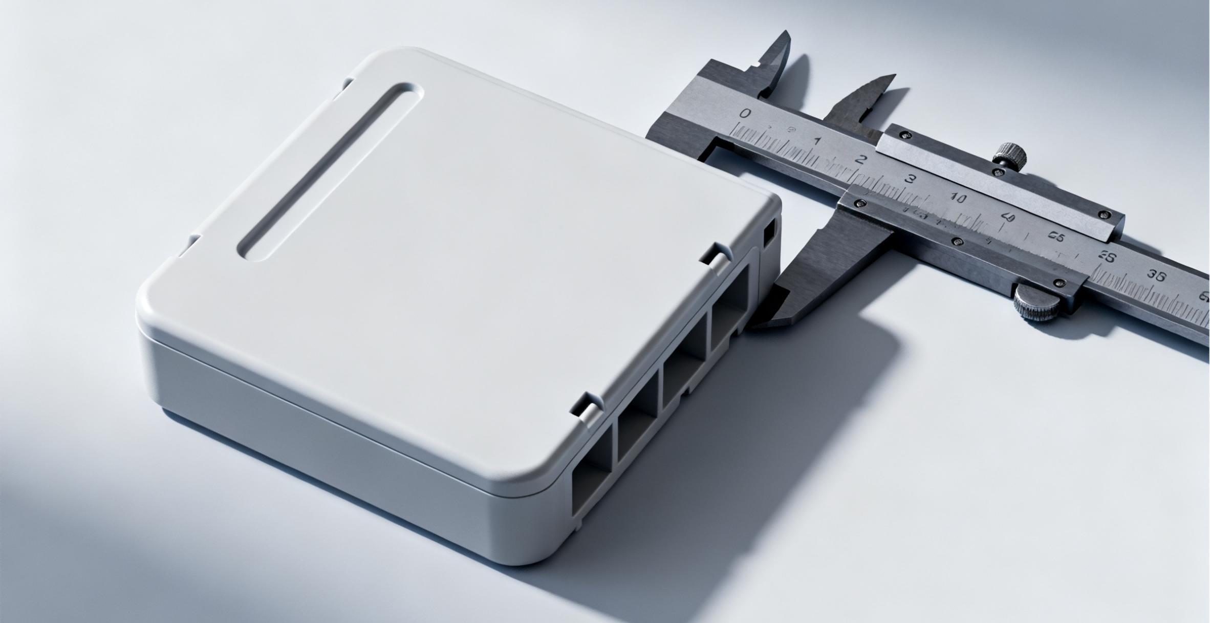
Reading a Sink Mark: Where Thick Sections Pull the Surface
Look first at where the mark is and what is behind it. The classic locations are:
- Opposite ribs — a rib that is nearly as thick as the wall it supports leaves a groove on the visible side.
- Opposite bosses — solid screw bosses create a ring or dimple on the outer face.
- Thick local pads or lugs — any local mass that cannot be fed during packing will shrink more than the surrounding wall.
- Near the end of the flow path — if the gate freezes before packing can reach a thick section, that section shrinks without compensation.
A sink mark and a warp or flatness problem often share the same root cause: uneven shrinkage. So the first diagnosis question is not “what process setting removes this mark” but “where is the uneven mass and can the design reduce it.”

Wall Thickness and Rib Design That Prevent Sinks
Most sink marks are designed in before the mold exists. The governing rule is to keep wall thickness as uniform as practical and to make internal features thinner than the wall they attach to. A common starting guideline is to size ribs at roughly 50–60% of the adjoining wall thickness and to add a radius at the rib base rather than a sharp corner; the radius reduces stress concentration and eases material flow, but the rib body should stay thin enough to avoid a thick junction.
Bosses follow the same logic. A solid boss around a screw hole acts like a thick pad and will pull the opposite surface inward. Practical approaches include cored bosses, thinner boss walls, and gussets sized like ribs. The drawing should carry the wall and boss dimensions as controlled features, not leave them to interpretation, because the molder cannot fix geometry that is already locked in.
When a thick section is genuinely unavoidable, say so on the drawing and place it where the cosmetic impact is acceptable, or plan a gate and feed geometry that can pack it. Mold-flow analysis is worth running before tooling when a visible class-A surface sits opposite a thick feature.
Process Levers: Packing, Gate Size, and Cooling
Once the mold exists, the process can still remove or reduce many sink marks. The main levers are:
- Packing pressure and time. Higher hold pressure pushes additional material into the cavity before the gate freezes, compensating for shrinkage. Packing time must last until the gate area is frozen; cutting it early lets thick sections shrink freely.
- Gate size and location. A larger or differently placed gate keeps the feed channel molten longer and lets packing reach the thick section. Gate changes are mold work, not a machine setting, so they are the later, more expensive lever.
- Cooling balance. Even cooling around thick and thin sections reduces the shrinkage gradient. Mold temperature adjustments can help, but they interact with cycle time and other defects.
- Melt temperature. Temperature changes affect viscosity and shrinkage; the right direction depends on the material and the part, so change one variable at a time and record the result.
Process fixes have a limit. If the geometry creates a thick section that the gate cannot feed before freezing, no amount of packing pressure will fully compensate. That is why the order of attack matters: design first, then process, then mold changes.
Sink Mark vs Void: Telling the Problems Apart
A sink mark is a surface depression. A void is an internal cavity left inside the part when the shrinking core cannot pull material from anywhere and instead opens up. The two can appear together: the surface sinks partway, and the remaining shrinkage opens a void underneath.
Differentiating them matters because the fixes differ. A visible sink with no internal void usually responds to better packing and thicker feed geometry. A part with internal voids may need packing changes, lower shrinkage material, or a different gate location, and the void may only be confirmed by sectioning, density checks, or X-ray/CT inspection on critical parts. If a molded part is failing in service and no surface defect explains it, do not assume the surface tells the whole story.
Fixing Sink Marks on Parts Already in Production
When parts are already running, work through the diagnosis in a fixed order and change one variable at a time:
- Confirm where and when the mark appears. Is it every shot, only at certain cavity positions, or only after a machine or material change? That pattern points to geometry, cooling balance, or process drift respectively.
- Check the design intent. Compare rib and boss thickness with the wall on the drawing. If internal features are thicker than the wall, the geometry is fighting the process.
- Increase packing pressure and extend packing time in small, recorded steps until the gate freezes; watch for flash, part weight, and ejection problems that come with overpacking.
- Evaluate gate and runner geometry. If the gate is small or located far from the sinking section, that is the structural reason packing cannot help.
- Review cooling. Uneven cooling across the sinking area can be corrected with mold temperature adjustments or cooling-line changes.
- Consider material. Lower-shrinkage or filled grades reduce sink tendency, but changing material affects every other property and requires revalidation.
- Document and repeat. Record the settings, part weight, and visual result for each step so the next trial starts from data instead of memory.
Diagnosing sink marks on the production floor
A production example shows the diagnostic order working. A molded panel develops a faint line opposite a rib on every shot, and the first response is to raise the packing pressure. The line improves but does not disappear, and the operator records the result — the pressure is near the flash limit, and the line is still visible. The next step checks the design: the rib is thicker than the wall it supports, so the geometry is the cause, and no packing change can fully remove the sink without overpacking the part. The tooling review proposes two options: core the rib to reduce the mass, or move the gate so the packing reaches the rib before the gate freezes. The design change is approved because the geometry is the root cause, and the revised rib eliminates the sink at a normal packing pressure. The example shows why the order matters: the process lever was tried first because it was free, the design was diagnosed when the process hit its limit, and the tooling change was justified by the evidence rather than by the guess. A sink mark that is chased with pressure alone can run for weeks, flashing the part and masking the design cause that the drawing review would have found in an hour.
The same diagnostic discipline applies to the parts that mix design and process causes. A boss that sinks opposite a thick wall may respond partially to packing and fully to a cored boss; a thick pad that sinks only in the summer months may be a cooling or a material issue; and a sink that appears after a material change may be a shrinkage difference in the new lot. Each case is diagnosed by the pattern, the history, and the design review, and the fix is chosen for the cause. The trial record — the settings, the part weight, and the visual result at each step — is what makes the diagnosis repeatable and the fix verifiable, and it is the evidence the molding team and the design team share when the change is proposed. When the sink mark is diagnosed in order, the part that was failing becomes the part that teaches the process — and the fix that ends the defect is the fix that the evidence supported.
For a new program, reviewing the part model before the mold is cut is faster than any molding trial. The wall-thickness map, the rib ratios, and the boss designs are visible in the CAD model, and a mold-flow study can show the sink risk while the design can still be changed at a drawing cost rather than a steel cost.
If a sink mark is only a cosmetic concern on a textured surface, a surface texture can make a minor mark less visible — but that hides the symptom without fixing the cause, and it will not help a functional surface. When the fix requires mold work, the plastic injection molding team can review the part, the gate layout, and the trial data together before you commit to cutting steel. If the part is still on the drawing board, catching an over-thick rib or an uncored boss at review is cheaper than any packing-pressure adjustment made after the mold exists.