

Two numbers decide whether a thin moulded lighting part comes out clear or comes out with a bent frame and a sink mark on the face: the wall section, and the rib that supports it. Thinness and light transmission pull in opposite directions in the tool, and the design work happens in the gap between them.
Last updated:
Why Thin and Transparent Pull Against Each Other
A light-transmitting part wants a thin wall, because the thinner the section the less material the light has to cross. A stable, elegant luminaire wants a stiff wall, and a stiff wall is a thick one. Every compromise between the two shows up in the same two places: on the lit face, where a locally thick section cools more slowly and pulls a sink mark into the surface, and at the frame, where an unbalanced wall section cools unevenly and bows.
The other constraint is the process. A wall that is routine in aluminium on a CNC machine may be impossible to mould in a stiff thermoplastic without sink or warpage, and a section that fills cleanly in one resin can short-shot in another. That mismatch is the single most common reason a thin-wall design fails on the first tool rather than on the third, and it is a design decision made before the tool is cut.
Where the Mould Design Carries the Risk
Once the wall section is fixed, the mould has to hold it. The levers that matter most in a thin-wall tool are the steel grade, the cooling layout, the gate and any inserts that can be replaced without scrapping the block:
| Design lever | Effect on durability | Upfront cost | Use it when |
|---|---|---|---|
| Higher-grade steel (H13) | High | Higher | Abrasive or high-temperature material |
| Optimised cooling channels | High | Moderate | Long runs and tight dimensional control |
| Replaceable gate inserts | High | Low to moderate | High-shear gating or filled resins |
| Hard coatings (PVD and similar) | Medium to high | Moderate | Wear at slides, cores and pins |
The cooling arrangement decides how uniform the thin section actually is. Straight drilled channels suit simple prismatic blocks; baffles and bubblers reach deep or narrow cores; high-conductivity inserts pull heat out of local hot spots; and conformal cooling follows complex three-dimensional geometry at a higher cost. On a thin translucent part, that uniformity is not only a warpage question, it is a visual one, because uneven cooling leaves a visible flow or haze difference across the lit surface. These levers and their cooling options are set out in the shop’s guide to precise custom mould design.
The Project This Page Comes From
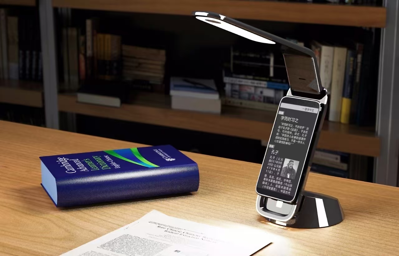
A bespoke pendant light was developed for an international client against specifications that were genuinely exacting. Every lamp piece had to be extremely thin while reaching a high level of light transmittance, and the two requirements conflict by nature: thinness usually costs transmission, and transmission usually wants a clean, uniform section. The luminaire also had to read as an elegant, stable object while being built from components that were individually fragile.
The obstacles were concentrated in structure rather than in surface. Optimising the product structure meant balancing the fragility of the thin lamp pieces against the stability and aesthetic integrity of the whole fitting; the engineers worked through the geometry so that the light would hold its shape as well as its appearance in daily use. The mould structure required its own round of work. Traditional mould designs would not deliver high-precision thin parts, so the team explored different mould geometries and cooling arrangements to find the balance between production efficiency and the quality of the finished piece. Two months of design-studio simulation and workshop trials followed, with designers, engineers and technicians working through setbacks in the same loop. The parts finally delivered met and exceeded the client’s specification, with thin sections that let light through cleanly.
Ribs, Sinks and the 50–60% Rule
The rib is where a thin-wall design usually fails, because the rib is thick exactly where the cosmetic face is thin. A common starting guideline is to size a rib at roughly 50–60% of the adjoining wall thickness and to radius the rib base rather than leaving a sharp corner. Run the arithmetic on a 2.5 mm wall: the rib belongs at about 1.4–1.5 mm, not at 2.5 mm. A rib that matches the wall creates a locally thick section that cools last, and the shrinkage arrives at the visible face as a sink mark.
Those figures, and the distinction between a sink mark and an internal void, come from the shop’s notes on sink marks in injection moulding. The practical consequence for a luminaire is that the stiffening structure belongs behind the lit face wherever the design allows it, so the flow and the cooling stay balanced on the surface people actually look at.
What to Ask For on a Thin-Wall Moulding Order
Thin-wall tooling is expensive to change and slow to prove, so the records are the cheapest insurance available: the DFM review that fixed the wall section and the rib proportion before the tool was cut, a first-article inspection report, wall-thickness measurements from a sectioned sample or an ultrasonic gauge, a light-transmittance or colour check on a production piece where the appearance is part of the specification, and the mould maintenance record once the tool is in service. Where a shop cannot measure a property on the real part, the honest answer is that it is available on request rather than assumed from the drawing.
FAQ
How thin can a moulded light-transmitting part be?
It depends on the resin, the flow length and the finish, not on a single number. The controlling test is whether the section fills cleanly and cools evenly at the gate and at the last point to fill. If a wall that machines cleanly in aluminium is being moved into a stiff thermoplastic, expect to increase the section or change the material.
Why does a thin wall develop sink marks when ribs are added?
Because the rib is a locally thick section, and thick sections cool last, so their shrinkage pulls at the visible surface. Size ribs at roughly 50–60% of the adjoining wall thickness and add a radius at the rib base: a 2.5 mm wall takes a rib of about 1.4–1.5 mm, not a rib of 2.5 mm.
Does cooling design change the appearance of a translucent part?
Yes. Uneven cooling leaves a visible haze or flow difference across a lit surface, even when the part is dimensionally within tolerance. Baffles, bubblers, high-conductivity inserts and conformal cooling all exist to make the temperature field more uniform, which is why cooling is a cosmetic decision on a lighting part and not only a cycle-time one.
Should stiffening structure go on the visible side of a lamp housing?
Where the design allows it, no. Keep ribs and bosses behind the lit face so the flow and cooling stay balanced on the surface people see. Where structure must be on a visible face, expect the tool to need texture, a heavier wall balance, or both.
What documents should come with a thin-wall moulded order?
The DFM record that fixed the wall and rib proportions, a first-article inspection report, wall-thickness measurements, an appearance or light-transmittance check on a production piece if the look is specified, and the mould maintenance record once production is under way.
Latest Post
Vacuum Casting VS Injection Molding: How to Choose the Right Manufacturing Process from Prototype to Production
History of CNC Machining: The Origins and Development of Computer Numerical Control

The Ultimate Guide to Injection Molding: Process, Types, Advantages & Applications

How to Choose the Right 3D Printing Process: An Analysis of Pros and Cons

What is CNC Machining?A Complete Guide to Processes,Advantages,and Applications
Medical Mold Making: Where Medical Tooling Differs From Ordinary Tooling
3D Printing Tolerance for Tight Fit: Clearances That Actually Snap Together
3D Printing Tolerance Test: Building a Coupon That Tells You the Real Numbers
Medical Device 3D Printing: Which Parts Suit Additive, and Which Do Not