

The Origins of 3D Printing
The initial contact might feel a bit confusing, but you must know that adding bricks layer by layer to build a building is quite similar to the principle behind 3D printing.
Last updated:
The origin of 3D printing can be traced back to the 1980s. In 1983, American engineer Charles Hull invented “stereolithography” (SLA), which is considered the first 3D printing technology. He used ultraviolet light to cure liquid photopolymer resin, solidifying it layer by layer to create a three-dimensional object. This is why he’s often referred to as the “father of 3D printing.”
The Working Principle of 3D Printing
3D printing, also known as additive manufacturing, is the opposite of subtractive manufacturing techniques like CNC machining. Its working principle involves breaking down a complex three-dimensional structure into countless two-dimensional planes, building it up layer by layer to turn a virtual model into a physical object. This overcomes the limitations of traditional subtractive methods (such as cutting) in terms of geometric shapes.
Stereolithography technology was initially used for rapid prototyping, and its key advantage lies in its ability to efficiently create physical prototypes of new parts and products.
Why is 3D printing so popular?
How Does 3D Printing Work?
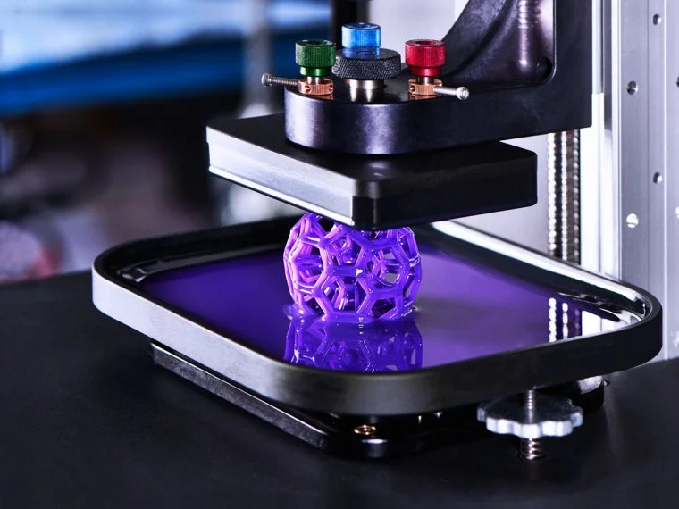
What Are The Common 3D Printing Technologies?
SLA (Stereolithography):
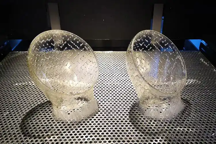
SLA is a 3D printing technology based on photopolymer resin curing. The principle involves using a UV laser to scan and cure the resin point by point in a liquid resin vat, forming a thin layer. After each layer is cured, the build platform lowers by one layer thickness, allowing fresh resin to cover the cured layer. The process repeats, curing the resin layer by layer to ultimately form a three-dimensional part. After the formation is complete, excess resin must be cleaned off, and secondary UV curing is performed to enhance the mechanical properties and stability of the part.
Advantages of SLA:
High precision, with errors controllable within ±0.1mm. Smooth and delicate surface finish, with high detail reproduction. A wide variety of photopolymer resins available to meet different needs,Relatively fast printing speed (especially for small-sized parts) and low cost.
Disadvantages of SLA:
Long-term stability is insufficient; parts exposed to sunlight or UV light for extended periods may experience aging, yellowing, and performance degradation. Low strength, limiting its suitability for functional testing.
Applications:
SLS (Selective Laser Sintering)
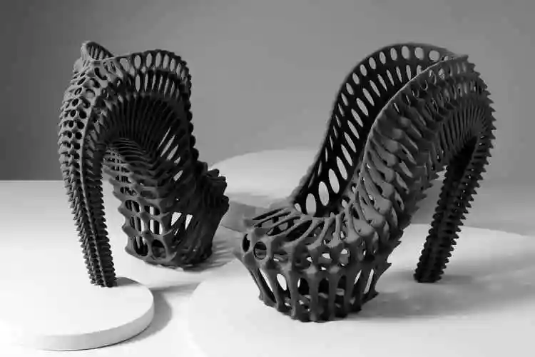
Infrared lasers or CO2 lasers are used to scan and sinter the powder bed layer by layer: First, the metal powder is uniformly heated to a temperature slightly below its melting point using a preheating system. Then, the laser beam scans according to the cross-sectional data of the 3D CAD model, causing the powder particles to fuse and form under the thermal influence. Un-sintered powder particles naturally form a support structure, preventing collapse in areas with overhangs. After sintering one layer, the build platform moves down 0.1-0.3mm along the Z-axis, and the powder spreading device evenly lays down a new layer of powder. This process is repeated until the entire part is formed.
Advantages of SLS:
Excellent mechanical properties.
Products are sturdy and durable.
Excellent corrosion resistance.
Disadvantages of SLS:
Printed parts may have a noticeable grainy texture on the surface.
Dimensional accuracy is lower than SLA.
Large parts may experience deformation issues.
Applications:
FDM (Fused Deposition Modeling)
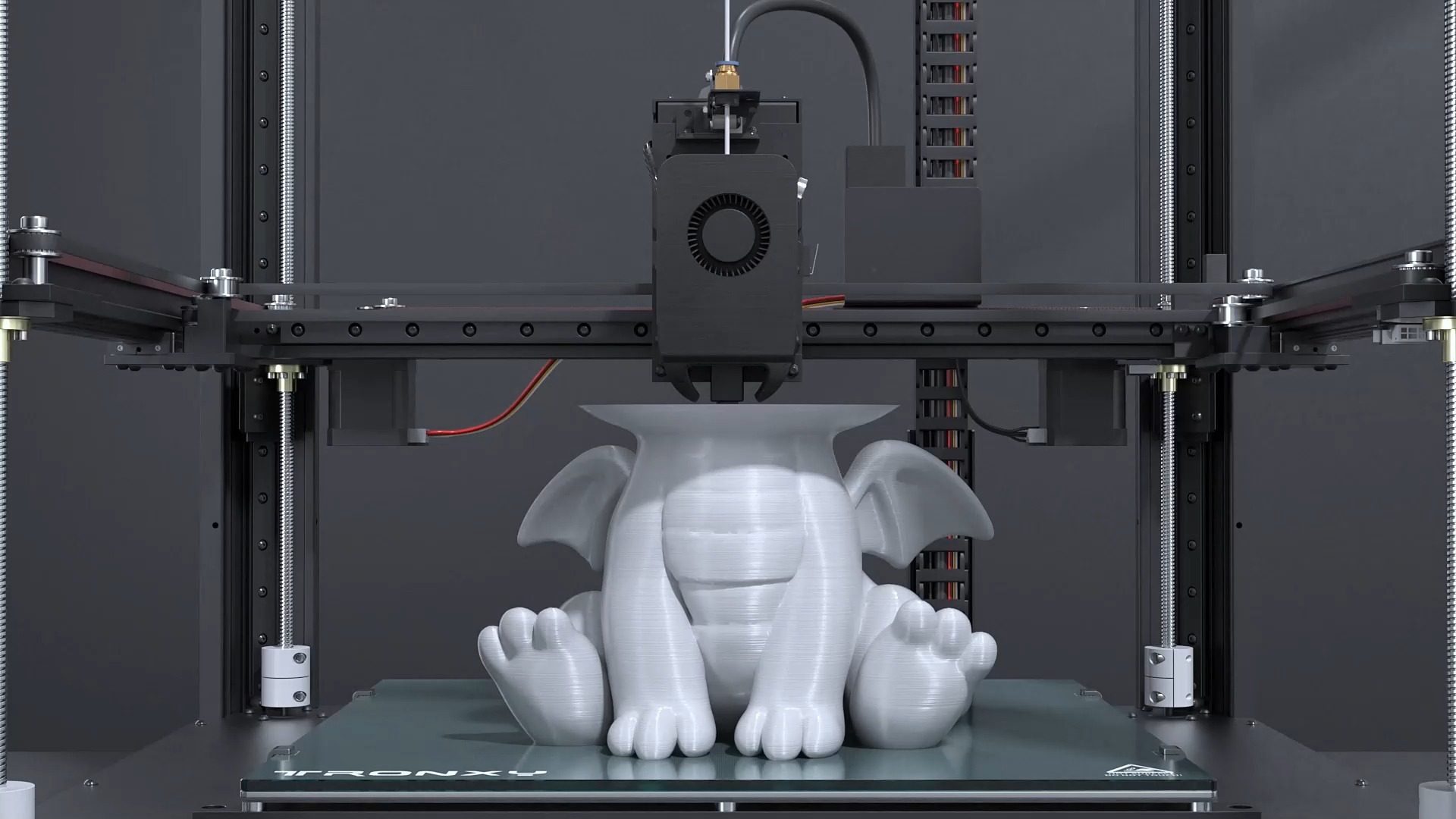
The filament material (wire) is fed into the nozzle through a feeding mechanism. An integrated heating device inside the nozzle melts the filament into a semi-liquid state. The nozzle moves along the sliced path on the print bed, extruding the molten material and depositing it in the specified locations. The material quickly cools and solidifies to form one layer of structure. After each layer is completed, the platform lowers (or the nozzle rises) by the thickness of one layer, and the extrusion and curing process is repeated until the part is fully formed.
Advantages of FDM:
Low equipment and material costs.
A wide variety of materials available, with high safety.
Offers a certain level of strength.
Disadvantages of FDM:
Lower precision, with noticeable layer lines and rough surface finish.
Limited suitability for functional testing.
Low strength in the Z-axis direction.
Applicable Scenarios for FDM:
Rapid prototyping to verify structure and assembly relationships.Suitable for functional parts that require chemical resistance or high-temperature resistance.
SLM(Selective Laser Melting)
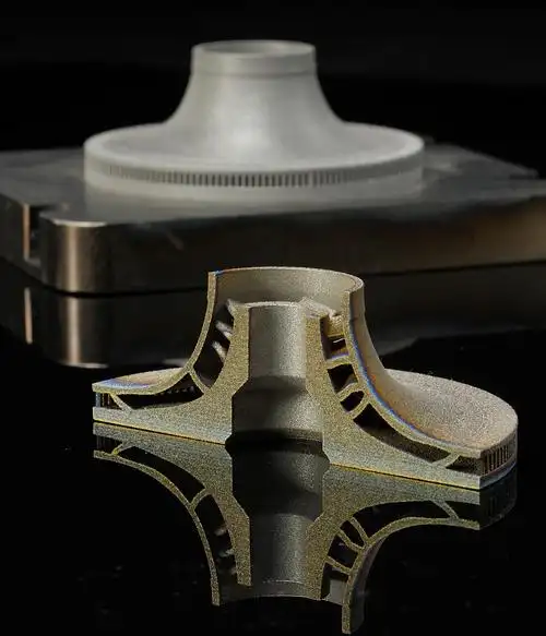
Advantages of SLM:
High part density, approaching or even equivalent to forged material performance. Capable of producing parts with complex geometries.
Disadvantages of SLM:
Low efficiency, not suitable for mass production.
High cost.
Rough surface finish, usually requiring post-processing or surface treatment.
Applicable Scenarios for SLM:
Suitable for parts with complex structural shapes.
Suitable for high-strength, high-hardness, wear-resistant, and high-temperature functional metal parts.
One-piece formation reduces the need for metal components in assemblies.
MJF (Multi Jet Fusion)
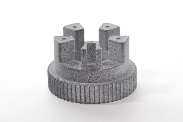
The principle of MJF (Multi Jet Fusion) technology involves first laying a layer of polymer powder on the build platform. Then, a selective application of fusing agent and detailing agent is sprayed. Infrared light is used to rapidly melt and solidify the areas sprayed with the fusing agent, while the detailing agent controls the precision of the surrounding areas. After each layer is completed, the platform lowers by one layer thickness, and the process is repeated layer by layer until the complete 3D part is formed.
Advantages of MJF:
Suitable for manufacturing strong, durable, and heat-resistant functional parts.
Uniform mechanical properties across parts.
Cost-effective.
Disadvantages of MJF:
Very large parts are difficult to print directly.
Potential risk of deformation.
Applicable Scenarios for MJF:
Parts requiring high strength and toughness.
Comparing the Processes by Tolerance and Fit
The process with the finest detail is not always the one that delivers the fit, and the cheapest process is rarely the one that holds an assembly. Published design bands put SLA around ±0.05–0.1 mm, SLS, MJF and metal processes around ±0.2–0.3 mm, and FDM at ±0.2–0.5 mm, which means the process choice decides whether a bore needs reaming before anything else is discussed.
| Process | Typical design tolerance | Best for | Where it disappoints |
|---|---|---|---|
| SLA | ±0.05–0.1 mm | Visual and detail parts, smooth surfaces, fine features | Support marks, brittleness, and UV ageing on exposed parts |
| SLS | ±0.2–0.3 mm | Functional parts, internal cavities, complex geometry | A grainy surface that needs finishing where it shows |
| FDM | ±0.2–0.5 mm | Lowest entry cost, quick iterations, real thermoplastics | Layer lines and direction-dependent strength |
| SLM and metal printing | ±0.2–0.3 mm | Metal parts and tooling inserts | Cost, support removal and distortion on thin sections |
| MJF | ±0.2–0.3 mm | Small-batch production in PA12 | Surface finish, and colour that is not uniform across a build |
The bands are the ones the shop publishes in 3D printing tolerances by process. Treat them as design starting points rather than guarantees: shrinkage and warpage are the silent variables, they differ between machines and even between positions in the same build, and a part that must fit another part is usually safer printed slightly undersize and finished.
A Worked Example: Sizing a Bore for a Printed Part
Assume a 6.00 mm bore that has to take a 6.00 mm steel dowel with a sliding fit, and that the print tolerance behaves like the published band. An FDM part at ±0.5 mm can land anywhere between 5.50 mm and 6.50 mm, so the worst case is an interference fit on one part and a 0.5 mm rattle on the next. An SLA part at ±0.1 mm lands between 5.90 mm and 6.10 mm, which is closer but still not a controlled fit.
The practical route is to stop treating the printed bore as the finished feature. Print the bore undersize — 5.80 mm is a reasonable starting point for a process with a ±0.2–0.3 mm band — then ream or bore it to the drawing after printing. That converts an uncontrolled printed dimension into a machined one, at the cost of one extra operation and a note on the drawing. The same logic applies to any mating feature: if it needs a class of fit, machine it; if it only needs to be close, print it.
For choosing between the three common plastics processes, the shop’s own selection table puts visual and detail work on SLA, functional thermoplastic parts on FDM or SLS, complex geometry with internal cavities on SLS, and the cheapest quick iteration on FDM, which matches the tolerance picture above: FDM vs SLA vs SLS.
What the Choice Costs Later
Three consequences are worth planning for before the file is released. A printed thread is a thread in name only, because the layer staircase changes the effective pitch diameter; print a pilot hole and tap it, or use a heat-set insert. A part that must be watertight needs a material and a wall thickness that closes the layer boundaries, which is not the same as a part that merely looks solid. And a print that will be handled daily needs the anisotropy understood: properties along the layers and across them are not the same, so the load path belongs on the drawing, not in the printer operator’s judgement.
What are the defects of 3D printing and methods to avoid them?
When 3D printing parts, DFM (Design for Manufacturability) guidelines should be followed to avoid the following issues: Following DFM principles is key to avoiding problems with 3D printed parts. The following points should be considered during the design process:
Be cautious of warping and deformation issues
Deformation of 3D printed parts can be caused by various factors, such as material properties, printing environment, and part design. Effective methods to prevent warping include optimizing the print orientation, reducing overhangs, adding support structures, increasing wall thickness, and incorporating reinforcement ribs in large surface areas to prevent sagging.
Avoid large overhang structures
In 3D printing, large overhang structures can cause issues because they require support structures underneath. This not only increases print time and material consumption but can also lead to a decrease in surface quality at the bottom of the overhang.
Avoid thin-walled structures
Post-Processing for 3D Printing
| Surface Finish Options | |
|---|---|
| Natural | Achieve a clean look with supported surfaces professionally sanded to remove any visible support marks. |
| Standard | Get a smooth, uniform appearance with sanded support areas and fine media blasting across the entire part, while subtle layer lines remain for an authentic 3D-printed look. |
| Custom | Elevate your parts with premium finishing options, including soft-touch coatings, high-clarity finishing, professional painting, masking, precise color matching, decals/graphics, and textured surfaces tailored to your needs. |
| Clear Coat | Clear cosmetic finish that can be applied to ABS-Like Translucent/Clear and PC-Like Translucent/Clear materials. |
| Painting | After smoothing the part with sanding and polishing,parts can be painted with automotive-grade paint. Provide a pantone color with your quote request.We also offer soft-touch painting. |
| Dyeing | Dyeing is another method for adding color to 3D prints. This is faster option with alimited color selection, so is a more cost-effective choice than painting. |
| Decaling | Decaling can be used to add a logo or other graphics to boost cosmetics or function. |
| Polishing | We can polish parts to a miror-like finish.If this is a requirement,we ask that you provide either a drawing or image that indicates your finish expectations. |
| Heat Treatment | Harden and strengthen metal 3Dprints with multiple heat treatment options: NADCAP heat treatment, hot isostatic pressing (HIP), solution annealing,and aging. |
| Machining | Machine metal 3D prints to achieve exceptional surface finish quality or meet tight tolerances. |
Whether you’re creating prototypes or producing end-use parts, additive manufacturing (3D printing) offers significant advantages. We provide a wide range of materials and processes, enabling ultimate geometric flexibility and rapid iteration, so you can receive high-quality parts in just a few days. For any questions about quotes or design, our applications engineers are ready to provide expert guidance and support to ensure your project runs smoothly. We look forward to collaborating with you on your next project!
What file formats are supported for 3D printing CAD files?
FAQ
What is the most accurate 3D printing technology?
SLA holds the finest band of the common plastics processes, roughly ±0.05–0.1 mm, with material jetting in the same class. SLS, MJF and metal printing sit near ±0.2–0.3 mm, and FDM is typically ±0.2–0.5 mm. Accuracy also depends on machine calibration and part orientation, so the band is a design starting point.
Is FDM or SLA better?
They answer different questions. SLA gives smoother surfaces and finer detail, which suits visual parts and small features. FDM uses real thermoplastics, needs no resin handling, and is usually the cheapest way to iterate a functional part. Choose SLA when the part must look right or hold fine detail, and FDM when it must behave like the production material.
Is STL or 3MF better for 3D printing?
3MF is the more capable format: it carries units, colour, materials and multiple objects in one package, and it is less prone to repair problems. STL still works everywhere but stores no units at all, so a file exported in inches can be printed as millimetres. If you send STL, state the units in the file name or the email.
Can a 3D printed part have internal channels?
Yes, with a powder-based process. SLS, MJF and metal printing build inside a powder bed and need no supports, so internal channels close and drain without a support-removal problem. FDM and SLA need supports inside the channel, which usually cannot be removed cleanly, so internal geometry belongs on the powder processes.
How do I hold a tight fit on a printed part?
Print the mating feature undersize by roughly one half of the process tolerance band and machine it to the drawing afterwards. A 6 mm bore in a ±0.2–0.3 mm process is a good candidate to print at about 5.8 mm and ream to size, which turns an uncontrolled printed dimension into a controlled machined one.
Latest Post
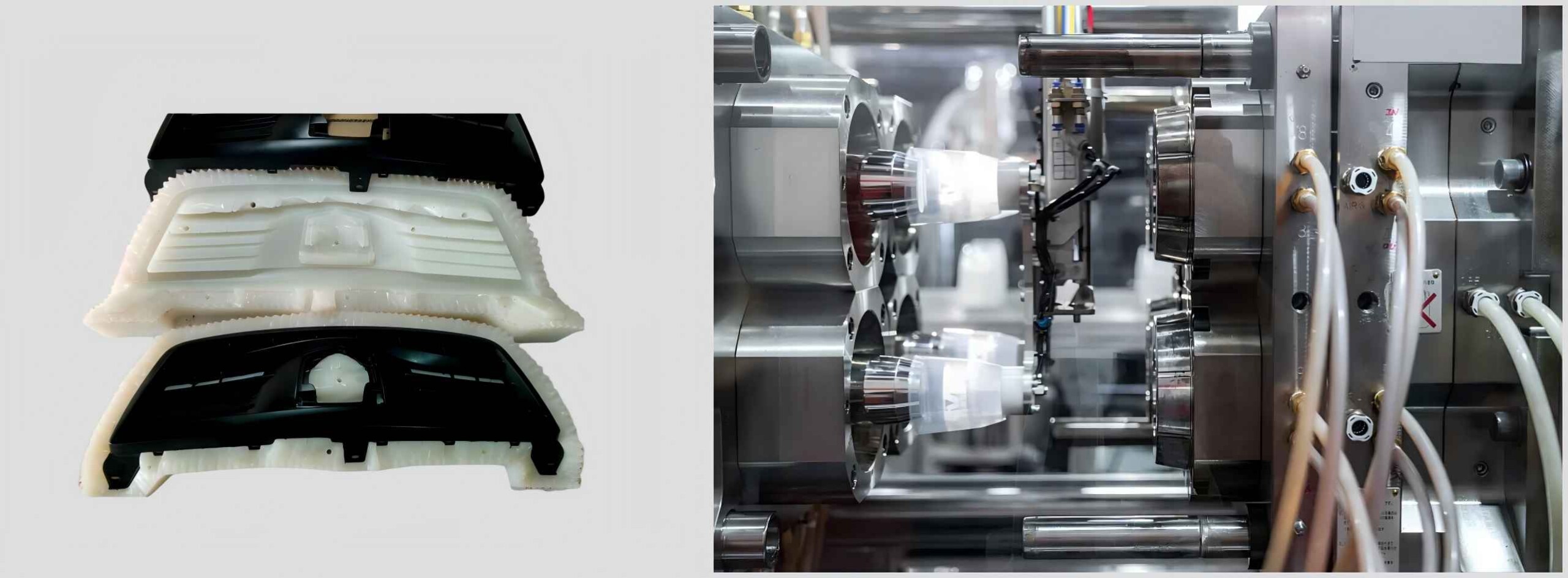
Vacuum Casting VS Injection Molding: How to Choose the Right Manufacturing Process from Prototype to Production
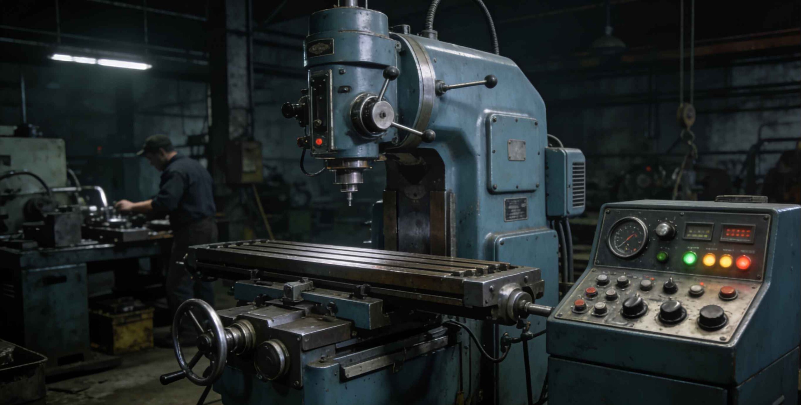
History of CNC Machining: The Origins and Development of Computer Numerical Control
The Ultimate Guide to Injection Molding: Process, Types, Advantages & Applications
How to Choose the Right 3D Printing Process: An Analysis of Pros and Cons
What is CNC Machining?A Complete Guide to Processes,Advantages,and Applications
Sheet Metal Enclosure Design: Corners, Sealing and Service Access
K Factor Sheet Metal Bending: Why the Same Model Gives Two Different Blanks
Custom Metal Fabricated Assemblies: Buying the Finished Item, Not the Parts
Laser Cut Prototypes: Flat Part Design and What the Cut Edge Gives You