

A molded panel comes out of the press looking flat, then bows 2 mm across its diagonal by the time it reaches final inspection an hour later. The molder checks the material certificate, finds nothing wrong, and the engineering team starts arguing about cooling time. The part is not defective in the way the certificate can show; it is warping because different regions of the geometry shrank at different rates and released that stress unevenly after ejection. Warpage is a whole-part distortion driven by shrinkage gradients, and fixing it requires reading those gradients — in the design, the cooling layout, and the process — in the right order.
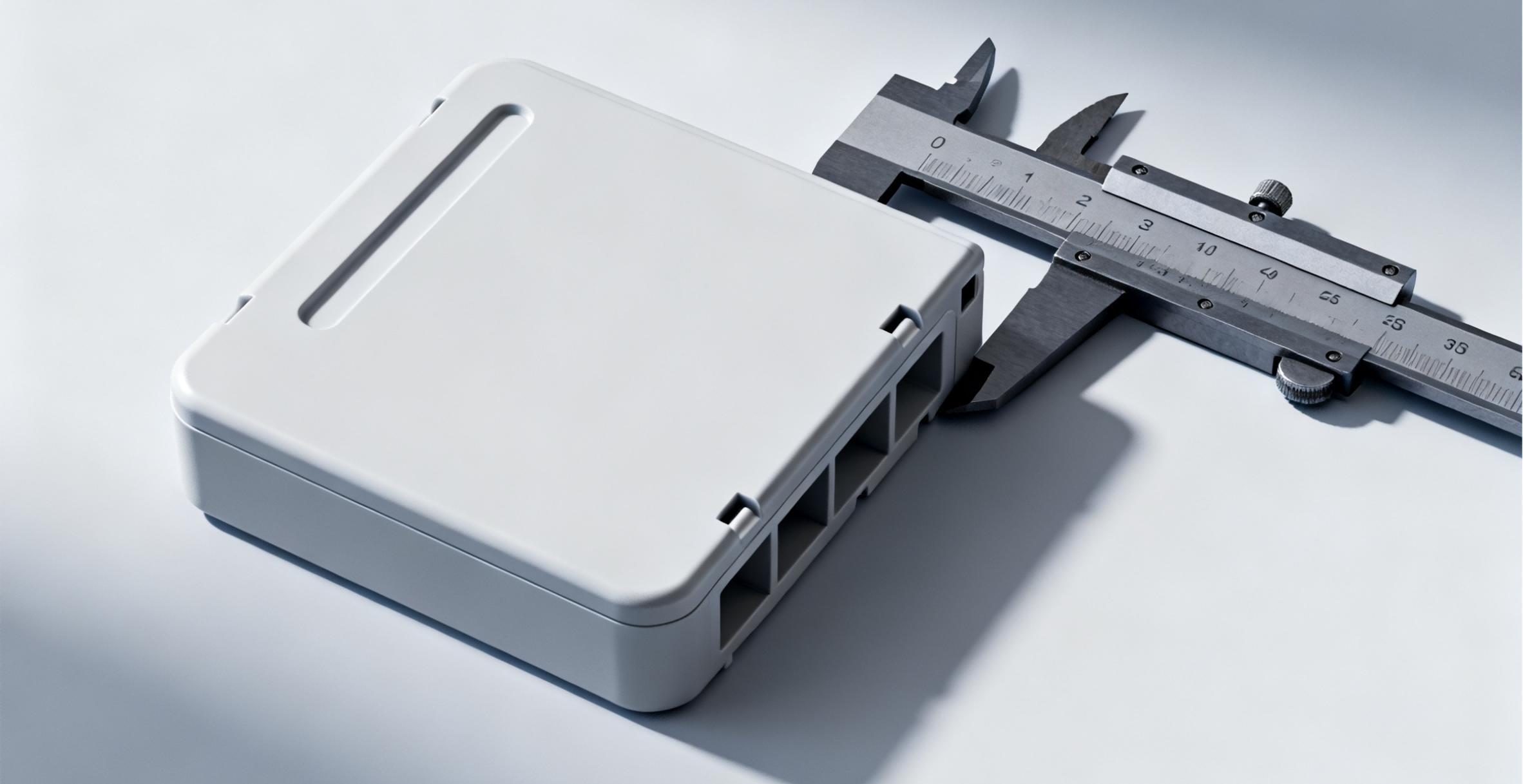
Warpage is uneven shrinkage, not high shrinkage
A molded part warps when shrinkage is uneven, not when shrinkage is high. Three asymmetries create the imbalance: geometry, where thick and thin sections cool at different rates; orientation, where flow direction produces different shrinkage along and across the polymer chains; and cooling, where one side of the wall freezes faster than the other. When the mold opens, the internal stress from those differences relaxes and the part bends toward the side that cooled last or shrank most.
This is why a flat part is not proof of low shrinkage; it is proof of balanced shrinkage. Two parts molded from the same material can behave differently if one has uniform walls and a center gate while the other has a thick boss at one end and an edge gate. Warpage analysis starts with the question “where is the shrinkage unequal?” rather than “what setting removes the bend?”
Wall balance and gate placement decide the shrinkage gradient
Wall thickness is the first lever: a part with uniform walls cools evenly, while thick sections act as heat sinks that keep shrinking after thin sections have frozen. Ribs and bosses add local mass and local stiffness at the same time — useful when placed to resist bending, harmful when they create unsupported thick junctions. Gate placement controls flow direction and therefore orientation shrinkage: a center gate on a flat panel fills it symmetrically, while an edge gate can leave a bow that follows the flow front.
Use ribs to resist the direction the part wants to warp, and keep them thin enough to avoid adding a second shrinkage problem. When a thick section is unavoidable, gate it so packing can feed it, and place it where the resulting stress does not bend a functional surface. Mold-flow analysis before tooling is the cheapest way to see these gradients; it predicts the warp direction even when the magnitude is uncertain.
The cooling side controls flatness over the run length
Cooling controls how fast and how evenly each surface freezes. If one cavity face runs hotter than the other, the part curls toward the hotter side after ejection because that side kept shrinking longer. Cooling-channel layout, mold steel choice, water temperature, and cycle consistency all contribute, and a part that is flat at the start of a run but bows by the end usually points to cooling drift rather than design error.
Mold-temperature changes are a legitimate process lever for flatness, but they interact with cycle time and other defects. Change one variable, measure the flatness at defined points, and record the part temperature at ejection and at measurement. Warpage often continues after ejection as the part finishes cooling or absorbs moisture, so the measurement time must be fixed; otherwise the numbers will disagree run to run even when the process did not change.
Warpage needs a fixture and a method, not a visual check
Warpage needs a fixture and a method, not a visual judgment. Place the part on a reference surface, measure the gap at defined points, or use a height gauge and a fixture that represents the assembly condition. Measure the same points every time, and record the time after ejection, because a part can be flat on the bench and bowed in the assembly, or flat at ejection and bowed an hour later.
Choose the measurement to match the function: a flatness zone on a sealing face is measured differently from a parallelism requirement between two mounting bosses. If the drawing says flatness over the whole surface but the function only needs flatness at the gasket line, say so, because tightening the wrong zone raises the cost of every fix. The design tips library on this site explains how to write GD&T flatness and parallelism so the molder and inspector measure the same thing.
What is the right order for correcting warpage?
Correct warpage from cheapest to most expensive, and stop when the data says the current lever is exhausted. Process first: packing pressure and time, cooling time, mold temperatures, and ejection behavior can remove a surprising amount of bow with no tooling cost. Handling second: warm parts ejected onto a stack or pulled by a robot arm can be distorted by forces the mold never applied. Geometry third: wall balance, rib placement, and gating changes on the drawing cost nothing before tooling. Mold work last: cooling-channel rebalancing, gate relocation, and ejection changes are the expensive levers, and they should be justified by measured parts, not by hope.
| Lever | When to try it | Cost class |
|---|---|---|
| Packing / cooling process | First trial shows directional bow | Process time only |
| Ejection and handling | Warp appears after part leaves mold | Fixturing / robot program |
| Wall balance and ribs | Warp follows thick sections | CAD change before tooling |
| Gate relocation | Bow follows flow direction | Mold modification |
| Cooling-channel redesign | Warp drifts with run length | Mold modification |
Each step should be documented with before-and-after measurements at the same points. If a change fixes flatness but creates flash or voids, record the interaction; warpage fixes often trade against other defects, and the trial record is what makes the next decision predictable. For a new program, the injection molding team can review the geometry and gate plan before the tool is cut, when the cheapest fixes are still available.
Material behavior sets the baseline for every warpage fix. Semi-crystalline materials such as nylon and polypropylene shrink more and show stronger directionality than amorphous materials such as PC-ABS, so the same geometry can warp in one material and stay flat in another. When a design is changed from one resin family to another late in the program, the warpage behavior changes even if the mold geometry is unchanged, which is why material substitutions deserve a full revalidation rather than a quick approval. Filler content works in the opposite direction: glass-filled grades shrink less overall but shrink more anisotropically, which can twist a part in a new direction. The practical tool is a mold-flow study run with the actual production grade, not a generic grade from the simulator library, because shrinkage models are grade-specific. If warpage appears only with certain material lots, compare the melt flow and shrinkage data on the certificates; lot-to-lot variation in flow can shift the filling and packing balance enough to show up as flatness drift. Keep the material grade and lot on the trial record so the warp history can be traced to the resin, not just to the mold.
Frequently asked questions
Can warpage be predicted before the mold is built?
Mold-flow analysis predicts the direction of warpage reliably and the magnitude approximately, because shrinkage models depend on material data quality and process assumptions. Use it to compare design variants and gate locations before tooling, then validate on the first shots. A simulation that predicts flatness perfectly is rare; one that predicts where the bow will be is common and valuable.
Does a higher packing pressure always reduce warpage?
No. Packing pressure that is too low lets thick sections shrink freely, but pressure that is too high can freeze in stress that releases as warpage after ejection. The correct packing window is the one that feeds the part without overpacking, and it depends on gate size and material. Increase packing in recorded steps, watch for flash and part-weight change, and measure flatness at each step.
Should the part be stress-relieved after molding?
Annealing can relax molded-in stress, but it also changes dimensions and cycle cost, and it is usually a band-aid for geometry that will keep warping in service. Use it for tight dimensional requirements on stable materials after confirming the temperature and time with the material supplier. The better fix is usually to balance the cooling and the wall sections so the part does not need the extra step.
Conclusion
Warpage is uneven shrinkage, and every correction starts by finding the asymmetry: in the wall sections, the flow direction, or the cooling balance. Measure at fixed points and times, correct from process to geometry to mold work, and record each step. The parts that stay flat are not the ones with the lowest shrinkage; they are the ones whose shrinkage was balanced on purpose.
If a new part is warping in trials or a production tool is drifting out of flatness, send the geometry, the measurement points, and the trial record to the 6CProto injection molding team. The fix order above works best when the data arrives with the part, not after the arguments.