
6CProto Engineering Guides
CNC Programming & Process Engineering Guides
Engineering references for cnc programming, toolpaths & cutting parameters.
Updated November 2026 · 24 articles
The toolpath is a cost decision, not a formality
Two programmers can produce the same part from the same model with cycle times that differ by a factor of two. The difference is not the software. It is the order of operations, the cutter engagement, the depth of cut, the number of retracts and the decision about which faces are finished in which setup. Programming is where the design meets the machine, and where most of the avoidable time is either removed or baked in.
The constraints are physical. A cutter can only remove material as fast as its flutes, its coating and the workpiece stiffness allow. A long, thin tool deflects; a deep pocket traps chips; a thin wall moves away from the cut. Good programming works with those limits instead of discovering them at the machine.
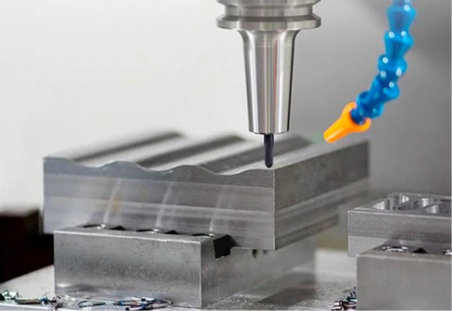
What the programmer needs from the design
A model, a drawing, the stock size, the fixture concept and the tolerances that matter. Without the fixture concept the programmer guesses which faces are accessible; without the tolerance list every dimension gets treated as critical and the cycle time reflects it. The most useful thing a designer can send is a short note naming the surfaces that must be finished in one setup and the features that can be approached from any direction.
Stock size is the other lever. A part machined from bar that is 2 mm oversize spends less time in roughing than the same part cut from plate with 10 mm of excess, and the price difference is entirely in the toolpath.
Where the time actually goes
Roughing removes most of the volume and finishing decides the tolerance. Adaptive or high-efficiency roughing keeps a constant chip load and uses the full flute length, which is why it beats traditional stepover passes on hard materials. Finishing is slower by nature, and the decision about which surfaces to finish — and to what roughness — is worth more than any feed-rate tweak.
The last item is verification. A toolpath that has been simulated against the actual stock and fixture is cheaper than a crash, and the simulation is only as good as the model of the holder and the vise that goes into it.
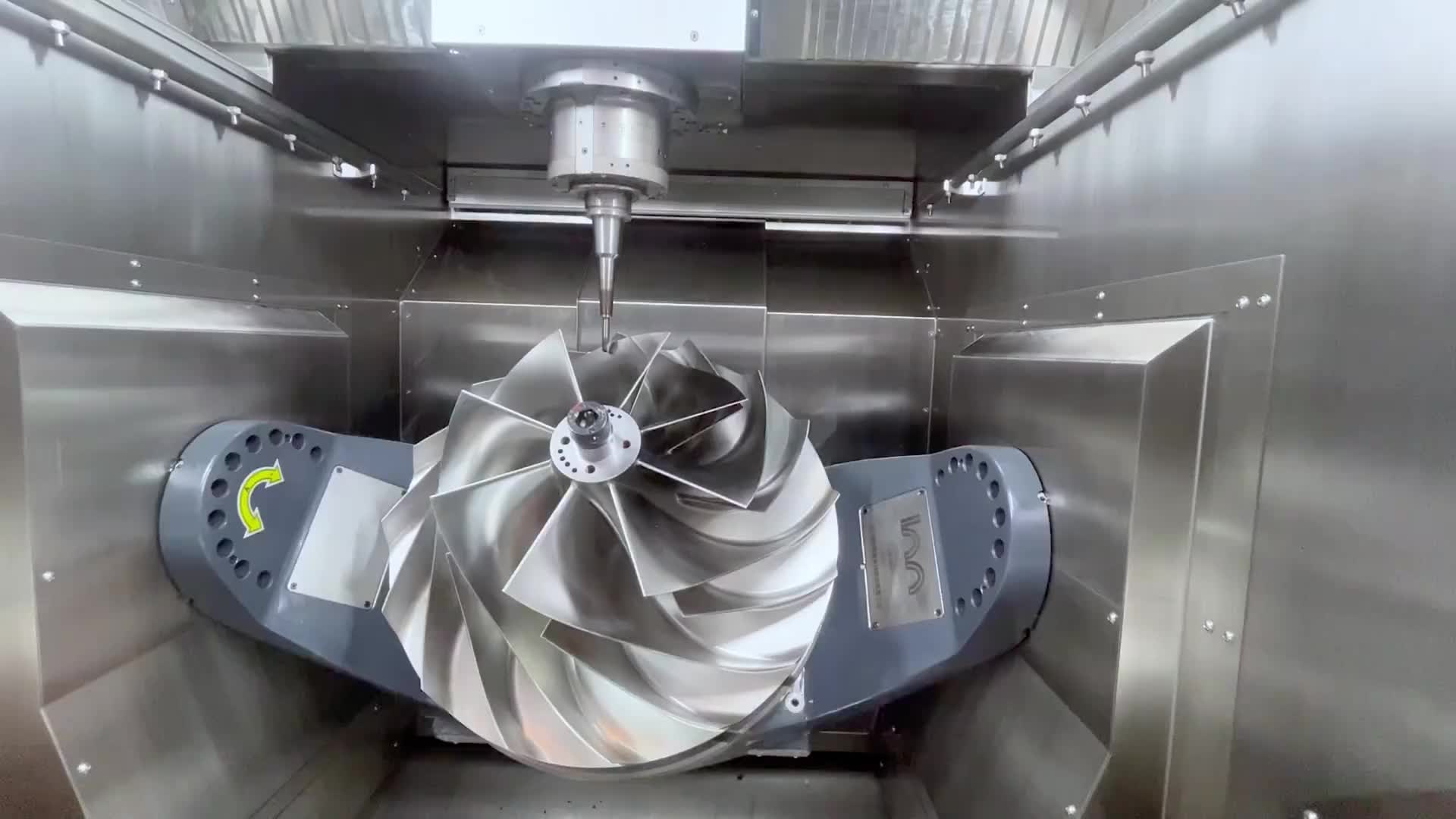
Simulation is cheaper than a crash
A toolpath that has been simulated against the actual stock, holder and fixture is the cheapest insurance in the shop. The simulation is only as good as the model that goes into it: a vise that is modeled 20 mm shorter than the real one, or a holder that is not modeled at all, turns a verified path into a collision at the machine.
The same discipline applies to the post-processor. A five-axis program that is correct in CAM and wrong in the post is a scrap part and a damaged spindle, which is why the first run of a complex program happens in air or in foam before it happens in metal.
Find the guide for your next decision
Follow the guide that matches the feature, failure mode or project decision you are working on.
Chip Load vs Feed Rate: Connecting Tooth Engagement to Programmed Feed
Sinker EDM Electrode Wear: Compensation, Detail Loss and Cavity Verification
G41 and G42 Cutter Compensation: Lead Ins, Side Selection and Verification
G96 vs G97: Constant Surface Speed and Fixed RPM in CNC Turning
G Code vs M Code: Motion Commands, Machine Functions and Controller Differences
G90 vs G91: Absolute and Incremental Coordinates Without Positioning Surprises
SFM to RPM: A Unit Checked Calculation for Milling and Turning
Climb Milling vs Conventional Milling: Choosing by Rigidity and Surface Requirements
Small Hole Drilling in Stainless Steel: Breakage, Chip Control and Verification
EDM Blind Cavity Flushing: Debris Removal Without Distorting the Feature
Copper vs Graphite EDM Electrodes: Detail, Wear and Manufacturing Trade-offs
Wire EDM Minimum Inside Radius: Wire Diameter, Spark Gap and Corner Control
Blind Hole Tap Drill Depth: Allowing for Drill Point and Incomplete Threads
Corner Radius vs Square End Mill: Tool Strength and the Geometry Left in the Part
Face Milling Surface Finish Problems: Reading Cutter Marks Before Changing Parameters
Welded Assembly Machining Allowance: Leave Stock Where Distortion Actually Matters
Stress Relieving vs Annealing: Choosing Heat Treatment Around Machining
Swiss Turning Cutoff Pip: Part Separation and End Face Acceptance
Swiss Machining Cross Hole Deburring: Sequencing Tools Around Small Features
Swiss Machining Bar Straightness: Incoming Stock Checks Before a Long Run
Sacrificial Features in CNC Machining: Tabs and Support Stock for Prototype Parts
Wire EDM Recast Layer: Surface Integrity, Finishing Passes and Acceptance
Face Milling vs End Milling: Matching the Cutter to the Surface and Access
Magnesium Machining: The Lightest Structural Metal and Its Safety Rules
Before you release the project
- Define the function, environment and the question this batch must answer.
- Specify material grade, geometry, quantity, finish and the dimensions that control fit.
- Agree the inspection method and the evidence required to accept the parts.
- Record the drawing revision and approval before production begins.
Common planning questions
Which CNC process should I consider first?
Start with the geometry. Rotational parts are usually candidates for turning; pockets and planar faces suggest milling. Tool access, setups and hardened features decide whether multi-axis machining or EDM adds value.
Should every dimension have a tight tolerance?
Specify tight limits only where fit or function requires them, and define how those features will be measured. Broad tight-tolerance notes can add cost without improving the part.
What should accompany the CAD model?
Provide a controlled drawing, material grade, quantity, critical dimensions, finish and inspection requirements. Identify cosmetic and sealing surfaces before the quote.
Move from guidance to a reviewed project
Send the CAD model and drawing with material, quantity, finish and inspection requirements. Use the relevant service page to review the available manufacturing route.