

Explore CNC Programming & Process Engineering Guides
A finishing pass can change direction and immediately change the surface, even though the cutter, spindle speed and programmed feed remain unchanged. The explanation is not simply that one direction is better. The tooth enters the material differently, the cutting force acts differently on the feed system, and the fixture may resist one loading direction more effectively than the other.
Climb milling vs conventional milling is therefore a setup decision as well as a toolpath decision. Climb, or down, milling starts with a thicker chip and progresses toward a thinner exit. Conventional, or up, milling develops chip thickness in the opposite progression. The useful choice depends on whether the machine and workholding can control the resulting engagement.
For a production review, separate the roughing objective from the finishing objective. Record the actual engagement and the surface being judged, rather than compare two programs whose stock, offsets and tool condition have also changed.
How does climb milling vs conventional milling change the chip?
Chip thickness progresses in opposite directions.
Climb milling enters with a thicker chip and leaves thinner material; conventional milling begins thin and builds thickness, changing rubbing, engagement and the force history within each tooth pass.
The Sandvik Coromant comparison of down and up milling explains the engagement distinction. Apply it to the actual side of the cutter in contact with the workpiece. On a pocket contour, a change in contour direction can change the local relationship; the screen’s clockwise appearance alone is insufficient without knowing spindle rotation and the material side.
The chip description does not set a permissible feed or guarantee a finish. Tool geometry, runout, material behavior and radial engagement still matter. At very light engagement, the effective chip thickness also needs attention rather than assuming the programmed feed per tooth represents every point on the cutting edge. Start the comparison by drawing the direction of rotation, feed and engaged material. That small sketch often reveals whether two proposed passes are actually being classified consistently.
At entry and exit, note whether the tooth crosses an interrupted edge. The engagement history can differ from the simple straight-wall case used to name the milling direction.
Backlash and machine rigidity
Climb milling can pull the work into the cutter when the feed system allows uncontrolled movement. Backlash, loose components or insufficient control of the axis can therefore change a nominally modest engagement into a much heavier cut. A modern CNC label does not independently prove that the particular machine and setup are suitable.
Review the condition and operating limits of the feed system before changing direction. The fixture, part and toolholder contribute compliance as well as the machine itself. A thin wall that deflects during cutting may recover afterward, so a finished surface can carry dimensional error even when the axis followed the programmed path.
The Sandvik milling troubleshooting guidance treats vibration and surface problems as interacting process conditions. Do not use a direction change to conceal a loose setup. Establish that the machine and workholding are serviceable, then compare feasible directions. Where the manufacturer’s instructions restrict an operation, those instructions govern the trial; a general preference for climb milling cannot override a specific machine limitation.
Workholding force direction
A fixture must resist the cutting force through a defined support and clamping path. Reversing the cut can move that force toward a stop, away from a stop, into a thin wall or toward an unsupported overhang. The same clamp locations can therefore behave differently under the two toolpaths.
Trace the load from the engaged material through the part and its supports into the machine table. Check whether a clamp depends on friction alone and whether an interrupted cut can unload a locating contact. Also consider when material removal weakens a section that initially appeared rigid. The last contour of a thin frame may be the most demanding fixture condition.
The Renishaw fixturing overview discusses repeatable support arrangements for measurement; machining fixtures additionally need to resist cutting loads. That distinction matters when the same part is located differently in production and inspection. In a milling process review, identify the wall or locating feature whose movement would change the accepted geometry, rather than describe the fixture only by its clamp count.
Different choices for roughing and finishing
Roughing and finishing need not use the same direction if they serve different constraints. Roughing may be limited by stock variation, interruptions or the stability of the blank. Finishing addresses a controlled allowance on the functional surface, often after the part has become less rigid.
Compare both operations within the actual sequence. A direction that gives a satisfactory finish on a solid test block may behave differently on the thin wall left after roughing. Likewise, a light finishing cut cannot be assumed to erase damage or deflection introduced by the earlier operation.
The Sandvik face-milling guidance shows how engagement and cutter position belong to application planning. Keep the roughing and finishing acceptance questions separate: material removal without instability, then geometry and surface quality on the final feature. The decision should be supported by those observations, not a universal statement that every finishing pass must use one direction. When a trial changes direction, preserve enough comparable stock to make the result interpretable.
Inspect the final wall thickness and support state when comparing finishing trials. A route proven before pocket removal may not represent the less rigid geometry present at the last operation.
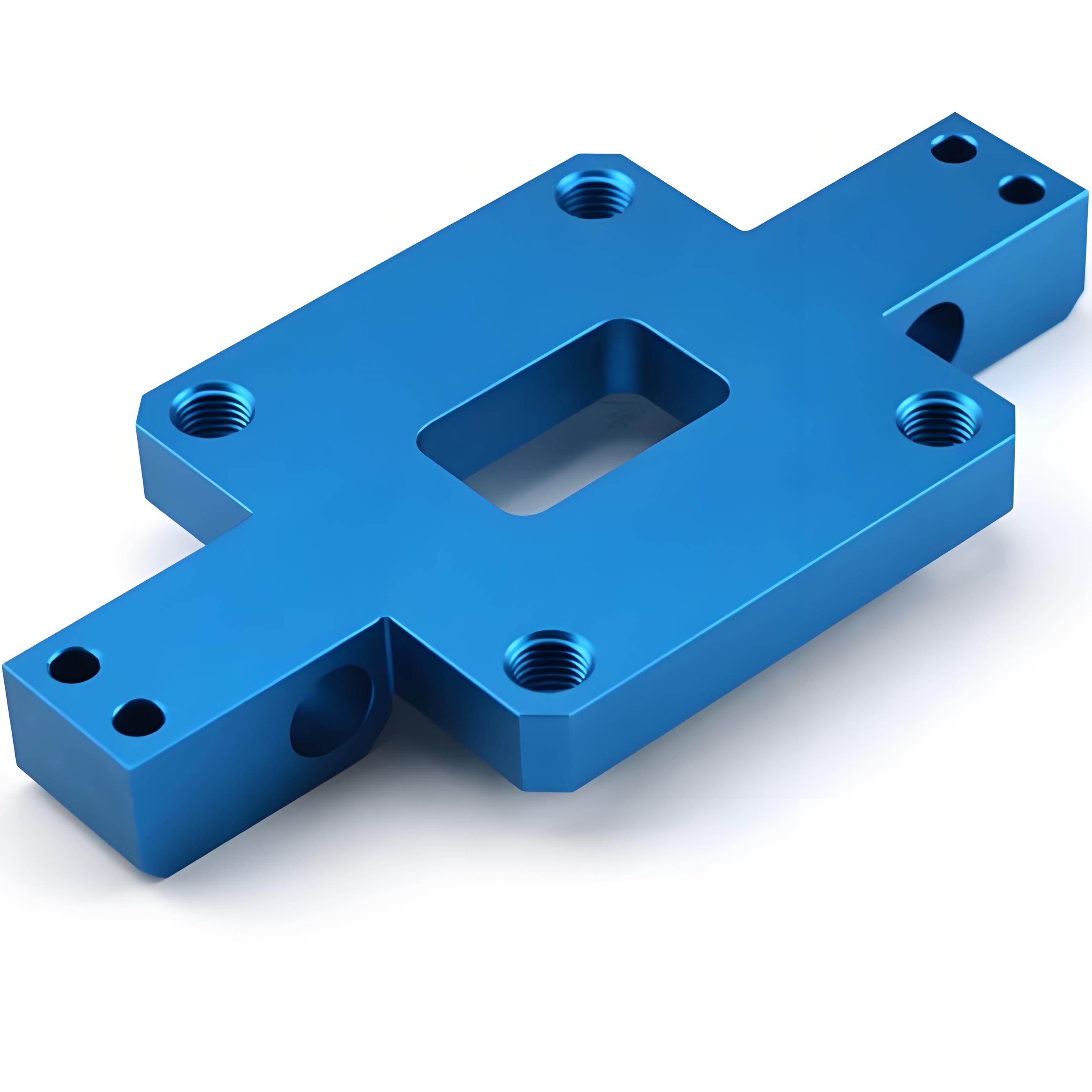
Engagement and setup comparison table
A fair comparison holds the relevant inputs constant while examining the effect of direction. Record tool identity, overhang, effective diameter, material condition, stock allowance and the surface to be evaluated. If one trial also changes the fixture, it is no longer a direction-only comparison.
Use the following table to identify the dominant constraint before selecting a trial. Each observation should lead to a specific process decision.
| Condition | Question for climb milling | Question for conventional milling | Evidence |
|---|---|---|---|
| Feed-system clearance | Could engagement pull the work unexpectedly? | Does the chosen direction control movement? | Machine condition and approved method |
| Thin wall | Where does the cutting load bend the wall? | Does reversing change support engagement? | Released-part dimensions and surface observations |
| Interrupted stock | How does the tooth enter each interruption? | Where does chip thickness build? | Comparable stock and tool-condition record |
| Final finish | Is the allowance sufficient and controlled? | Does rubbing or deflection dominate? | Specified surface and geometry measurements |
A process preference is useful only after the row that limits the actual setup has been addressed.
An annotated toolpath comparison
Assume an illustrative straight external wall finished with a vertical end mill rotating in a specified direction. Keep the material on one defined side of the travel path, and sketch the tangent motion of the engaged cutting edge. That establishes whether the feed follows or opposes the local cutting direction. No spindle speed or feed is prescribed by this geometry exercise.
Now reverse travel while preserving the same wall and spindle rotation. The engagement classification changes, but the programmer must also review the approach, exit and any corner transitions. Simply reversing a line in an existing program may leave an unsuitable lead-in or a move across an obstruction.
The Haas programming documentation provides a controller-specific example of why coordinate and offset states require review. The comparison should be simulated using the intended postprocessor and machine configuration. Record the material side on the annotated path so another engineer can reproduce the reasoning without relying on a screenshot whose rotation and viewing direction are ambiguous.
Simulation and first-part verification
Simulation can reveal unintended entry, excess engagement and interference with stock or fixtures when the model represents those items correctly. It cannot prove that an unmodelled loose clamp will remain stable or that the selected material will produce the expected surface. Physical verification still needs a controlled first-part procedure.
Agree which dimensions and surface characteristics will decide the trial. Measure the wall after the required release from workholding, and record tool condition and any visible chatter or tearing. A result measured while the part is elastically restrained can conceal movement relevant to final assembly.
The standards and tolerances discussion should be tied to the particular drawing callout, including the roughness parameter and measurement direction if surface finish is evaluated. Do not compare two numerical finish values obtained under different settings as though they isolated milling direction. Preserve the accepted toolpath, fixture and inspection method together so the production route retains the conditions that produced the approved result.

Process documentation and handoff
A released process should make the chosen direction visible at the operation level. Identify the workpiece side, tool and holder, fixture revision, stock allowance and the controlled program. A note saying climb mill is too incomplete if the next programmer cannot tell which surface and setup it describes.
Record why the choice was made. If a particular wall required a different finishing strategy because of its stiffness or clamp arrangement, that reason helps evaluate future changes. A new blank supplier, altered pocket depth or revised fixture can invalidate the earlier comparison without changing the part’s broad description.
For CNC machining procurement, specify the required part result and any essential approved process conditions without prescribing unnecessary machine details. Where the supplier owns the toolpath, request the acceptance evidence needed to demonstrate the geometry and surface condition. Where a qualified route must remain fixed, identify the change-approval requirement. This keeps a useful manufacturing choice from becoming an unsupported promise about every machine or cutter.
Keep the stock model synchronized with the released operation. A program revision that changes the remaining allowance can invalidate the comparison even when the direction label is unchanged.
FAQ
Does climb milling always leave a better finish?
It can improve the result in a suitable setup, but finish also depends on tool condition, engagement, workholding and material behavior. A direction change can worsen the result if it creates uncontrolled movement or loads a weak feature unfavorably. Compare the specified surface under matched conditions and measure the released part. A visual improvement alone does not demonstrate that the dimensions or surface-texture requirement have also improved.
Can a shop change the direction on a repeat order?
If the supplier controls the process and the purchase specification only controls the finished result, a change may be handled through its normal process controls. A project with an approved or qualified route can require additional review. The decision should consider the affected geometry and acceptance evidence, not just whether the same cutter is retained. Keep the new program revision and trial results connected to the repeat-order record.
Is a chatter-free simulation enough to release the operation?
A geometric simulation does not reproduce every aspect of cutting dynamics, material variation or fixture compliance. Its value is in checking the programmed route against the represented stock, machine and obstacles. Release still needs the physical evidence appropriate to the part, including the dimensions and surface condition that the operation controls. Treat simulation and first-part verification as complementary checks rather than two interchangeable ways to approve the same process.
Conclusion
Choose the direction that the feed system, fixture and evolving part geometry can control while meeting the operation’s actual objective. Chip formation explains the difference between climb and conventional milling; it does not remove the need to evaluate the complete setup.
A useful trial preserves comparable stock and inspection conditions, then records the reason for the accepted route. That evidence is more transferable to production than an isolated statement that one pass looked smoother. Revisit the decision when the support, engagement or critical wall changes.
6CProto’s CNC and DFM workflow can support a review of the relevant part geometry. Provide the drawing, functional surfaces and any approved process constraints for quotation, so manufacturing options can be compared against the same acceptance requirements.