

Explore CNC Programming & Process Engineering Guides
A broad top face and a narrow pocket floor may both look flat on the drawing, yet they rarely call for the same cutter or entry path. The face milling vs end milling decision depends on the surface’s size, adjacent walls, available approach space and the material left for finishing. A larger cutter can reduce passes across an open face while becoming the wrong choice as soon as a shoulder blocks its approach.
Treat the comparison as a process decision rather than a contest between tool names. The important result is a stable operation that produces the required plane, shoulder or pocket without introducing avoidable burrs, distortion or rework. The following checks connect cutter geometry and engagement to a practical manufacturing and inspection plan.
What separates face milling vs end milling in practice?
Choose by the surface and the cutter’s available access.
Face milling suits many broad accessible planes; end milling reaches narrower features and walls, while cutter design and approach clearance determine the feasible operation on each part.
A face mill normally presents multiple cutting edges across a broad working diameter, while an end mill offers peripheral and end cutting capability for a range of features. However, the categories overlap in practical use: an end mill can finish an open plane, and a shoulder milling cutter may produce both a face and a wall. Sandvik’s face milling guidance makes the operation and engagement more useful starting points than the label alone.
Check the approach before choosing diameter. A boss, clamp or raised wall can block the cutter body even if the inserts appear to clear. Include entry and exit space, holder envelope and the surface’s location in the fixture. The smallest drawing view often hides the collision that determines the route.
Show clamps and temporary supports in the access model. Clearance to the finished part alone can overlook hardware that occupies the cutter approach during the actual machining operation.
Axial and radial engagement
Axial engagement describes cutting depth along the tool axis; radial engagement describes the engaged width relative to the cutter. These affect chip formation, force direction and heat. A tool that appears conservative because it takes a shallow depth may still experience demanding engagement when it cuts nearly its full width.
Record both quantities for each operation, especially when a tool enters a corner. A pocket path can move from a light side cut into a much larger engaged arc without changing the programmed feed. Sandvik’s shoulder milling guidance discusses tool engagement and stability, while its milling formulas distinguish feed per tooth, spindle speed and table feed.
Do not transfer a surface speed or chip load directly between cutters with different diameters, tooth counts or engagement. The toolmaker’s data is a starting point for a specified material and tool system. Check the machine’s available speed, power, holder condition and coolant strategy. For a thin component, also assess the force direction relative to supports and the finished wall.
Record the engagement used for the selected tool data. Without that condition, another reviewer cannot determine whether the same feed assumption applies to a corner or wider cut.
Shoulders pockets and interrupted cuts
An open face offers more freedom than a shoulder or enclosed pocket. A shoulder operation must control the wall as well as the floor, while a pocket requires a feasible entry and chip evacuation route. An end mill selected for reach may need a long overhang, which changes the stability assessment even if its diameter is adequate.
Sandvik’s closed pocket guidance shows why cutter access and corner geometry must be considered together. An internal corner can increase engagement or limit the tool radius. Do not specify a finished corner that leaves no room for the chosen toolpath without reviewing the resulting loading and surface behavior.
Interrupted cuts create another distinction. Crossing a hole or thin edge changes entry and exit conditions and can affect burr formation or edge integrity. A CNC milling review should identify these interruptions on the model, not merely list the overall part dimensions. Protect critical edge lands and define any stock left for a separate finishing pass.
Check how chips leave the pocket as the feature becomes deeper. A feasible first pass does not establish that the final depth has the same evacuation and access conditions.
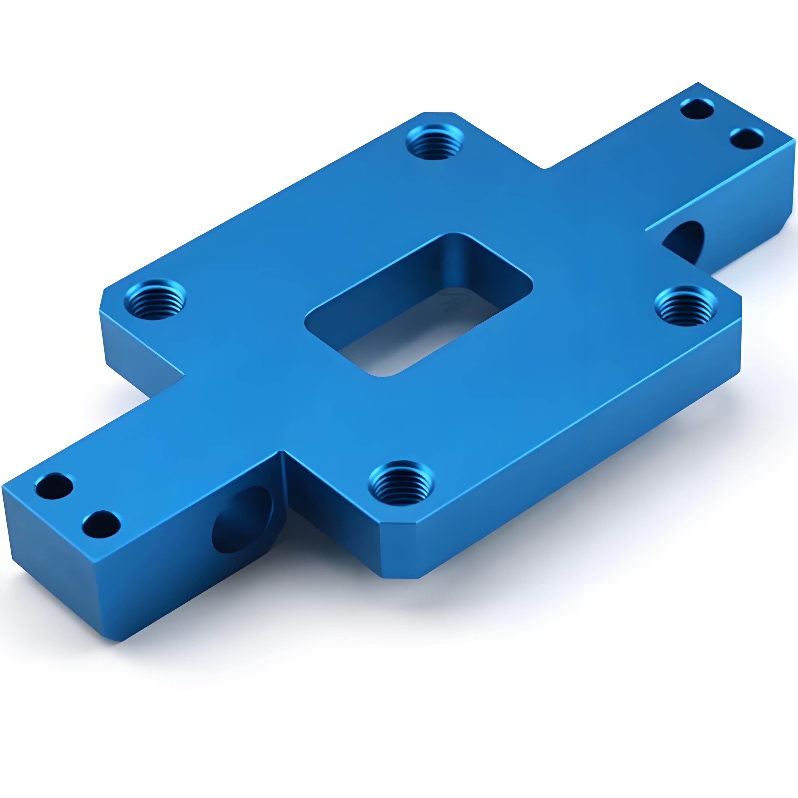
Comparing finish and setup requirements
A high productivity roughing operation does not automatically establish the final surface. Flatness, waviness, roughness and step marks respond to different aspects of the setup. Tool runout, spindle alignment, insert condition and component deflection can all affect the result, even when nominal cutting parameters are unchanged.
Specify the functional surface requirement before choosing a finishing strategy. A gasket seat may need a particular texture and continuous land, while a mounting face may be governed mainly by flatness relative to locating features. Do not substitute a visually shiny finish for either requirement. Sandvik’s milling troubleshooting guide connects common observations with multiple potential causes rather than a single universal correction.
Consider whether one setup can establish the required relationship between the plane and adjacent features. Reorienting a part for multi-axis machining access may solve an approach problem, but it also changes support and datum transfer. Choose the arrangement that can be verified on the finished component, not simply the one with fewer listed operations.
Plan inspection after the component reaches its specified free or assembled condition. A setup that holds a flexible plate flat can conceal deformation that returns after unclamping.
Units and controller compatibility checklist
A process comparison is incomplete until the units and programmed conventions are clear. Cutting speed and feed per tooth are tool data; the controller may require spindle speed and feed per minute. Confirm the selected mode before translating between them. A correct number in the wrong mode can create a severe mismatch.
| Check | Face milling implication | End milling implication |
|---|---|---|
| Available approach | Broad body and holder need clearance | Smaller diameter may reach constrained areas |
| Engagement | Entry position and width affect the cut | Corner engagement can rise sharply |
| Work support | Face loading may expose plate deflection | Side loading may bend walls or slender features |
| Verification | Plane form and surface texture | Wall, floor and corner relationships |
Check tool length and diameter offsets against the actual assembled tool. Haas’s mill programming manual illustrates controller specific offset and motion behavior; its conventions are not universal. The final setup sheet should name the units, feed mode, tool identification and compensation strategy so that a reviewer can reproduce the intended calculation.
Where the controller supports several feed conventions, include the selected convention on the review sheet. A unit label attached only to the spreadsheet does not establish program state.
Worked calculation or annotated toolpath example
For a hypothetical open plate, assume a cutter diameter of 50 mm, a selected cutting speed of 200 m/min, four effective teeth and a feed per tooth of 0.08 mm. These values illustrate the arithmetic only; they are not recommended parameters for an unspecified material or tool.
The spindle calculation is n = 1000Vc/(pi D), giving about 1,273 rpm. Table feed is vf = fz x z x n, giving 0.08 x 4 x 1,273 = approximately 407 mm/min. If a different tool has two effective teeth at the same speed and feed per tooth, its table feed is approximately 204 mm/min, not 407 mm/min.
Now consider a pocket that forces a smaller cutter and longer reach. Repeating the arithmetic is necessary but insufficient: engagement, evacuation and deflection change too. Sketch the actual entry and corner path before approving the tool choice. Check any rounding and controller mode on the setup record so the illustrative calculation is not mistaken for a released machining instruction.
Use the effective cutting diameter and active teeth for the actual tool configuration. A catalog family name alone is insufficient to reproduce the speed and feed calculation accurately.
Simulation and first-part verification checks
Simulation should represent the stock, fixture, holder and full tool assembly, not only the finished model. Examine approach moves, cutter entry, corners and retracts. A collision free display does not prove the workpiece will remain rigid or that chips can leave an enclosed pocket.
Use a first part to connect the modeled route with real evidence. Check the plane relative to the agreed datum, the shoulder position and any thin wall movement. For surface texture, specify the measurement method and location; the Mitutoyo surface measurement guide explains why a numerical roughness value depends on a defined measurement practice.
Compare the part before and after release from the fixture when clamping distortion is a credible concern. A flat plane measured under clamping load may change after unclamping. Define these conditions within the dimensional acceptance plan. If a result fails, relate it to the observed toolpath, support and tool condition before changing multiple parameters at once.
Retain the tool condition and measurement locations with the first part record. This makes a later finish change easier to investigate without guessing which surface was checked originally.

Process documentation and handoff notes
The handoff should explain why the route was chosen and what must remain controlled. List cutter identity, effective teeth, holder, overhang, material condition, stock allowance and fixture location. Include the roughing and finishing sequence, especially where a later cut changes the stiffness of an earlier finished feature.
Preserve the approved program revision and setup references with the first part results. If an insert grade, cutter diameter or fixture support changes, decide which calculations and measurements need to be repeated. A seemingly equivalent tool can change entry clearance, force direction or the residual stock at an internal corner.
For parts combining round and planar features, coordinate turned datum features with the milling setup. Do not assume that a turned outside diameter is automatically the correct datum for every milled face. The process record should connect each critical feature to a functional drawing requirement, leaving operators with a measurable target rather than an ambiguous instruction to achieve a good finish.
If a substituted cutter changes the internal corner stock, review later operations too. A downstream finishing tool may encounter a different engagement even when the roughing dimensions appear acceptable.
FAQ
Can an end mill replace a face mill on a wide plate?
It can be a practical choice when the machine, tool and required finish support the operation, but a wide surface will usually need more passes with a small cutter. Evaluate cycle time alongside step marks, tool deflection and available approach space. A large face mill is not automatically preferable on a flexible plate or light machine. Compare the complete setup and measurement result rather than selecting solely from cutter diameter or the number of passes.
Does a face mill always leave a smoother surface?
No. The result depends on cutter geometry, runout, insert condition, spindle alignment, material and workpiece support. An end mill may produce a better functional surface in a constrained or delicate feature, while a well set face mill can be effective on an accessible plane. Define the required texture and form separately, then inspect both. A reflective surface can still contain waviness or local geometry that prevents the component from performing its intended function.
Should the same feed be used for roughing and finishing?
Not automatically. Roughing and finishing may use different tools, engagements, stock allowances and objectives. A feed selected for one combination does not transfer directly to another, especially if tooth count or feed mode changes. Review the toolmaker data and actual remaining stock, calculate the programmed quantity in the correct units, then validate the first part. Keep a finishing pass purposeful; repeatedly taking an unsuitable light cut can introduce rubbing or unstable results rather than improvement.
Conclusion
Choose the milling route by the feature and the space available around it. An accessible broad plane often favors a face milling approach, while walls, pockets and restricted corners can make an end mill more useful. The decision becomes reliable when engagement, support, tool assembly and the required inspection are considered together.
Keep calculations tied to the actual cutter and controller mode, and distinguish surface appearance from flatness and texture requirements. A first part should confirm the intended relationship between the plane, its adjacent features and the assembly datums. When requesting a manufacturing review, provide the model, material condition and functional surface requirements for quotation. Those details are more useful than prescribing a cutter name without explaining the surface the component needs.
{“@context”: “https://schema.org”, “@type”: “FAQPage”, “mainEntity”: [{“@type”: “Question”, “name”: “Can an end mill replace a face mill on a wide plate?”, “acceptedAnswer”: {“@type”: “Answer”, “text”: “It can be a practical choice when the machine, tool and required finish support the operation, but a wide surface will usually need more passes with a small cutter. Evaluate cycle time alongside step marks, tool deflection and available approach space. A large face mill is not automatically preferable on a flexible plate or light machine. Compare the complete setup and measurement result rather than selecting solely from cutter diameter or the number of passes.”}}, {“@type”: “Question”, “name”: “Does a face mill always leave a smoother surface?”, “acceptedAnswer”: {“@type”: “Answer”, “text”: “No. The result depends on cutter geometry, runout, insert condition, spindle alignment, material and workpiece support. An end mill may produce a better functional surface in a constrained or delicate feature, while a well set face mill can be effective on an accessible plane. Define the required texture and form separately, then inspect both. A reflective surface can still contain waviness or local geometry that prevents the component from performing its intended function.”}}, {“@type”: “Question”, “name”: “Should the same feed be used for roughing and finishing?”, “acceptedAnswer”: {“@type”: “Answer”, “text”: “Not automatically. Roughing and finishing may use different tools, engagements, stock allowances and objectives. A feed selected for one combination does not transfer directly to another, especially if tooth count or feed mode changes. Review the toolmaker data and actual remaining stock, calculate the programmed quantity in the correct units, then validate the first part. Keep a finishing pass purposeful; repeatedly taking an unsuitable light cut can introduce rubbing or unstable results rather than improvement.”}}]}