

Explore CNC Programming & Process Engineering Guides
A faced surface with regular arcs, torn patches and a step between passes does not necessarily have one problem. Changing feed for all three can improve one symptom while leaving the geometry error untouched. The marks provide useful evidence when they are mapped to the cutter path and the part’s local support.
Face milling surface finish problems should be investigated before the original surface is polished away. Preserve a photograph showing feed direction, cutter travel and the affected region. Keep the insert and setup condition identifiable so the pattern can be compared with a specific cutting event.
The first decision is whether the complaint concerns texture, waviness, a step, flatness or visible appearance. These quantities can interact but are not interchangeable. A lower roughness reading at one spot does not prove that a broad face is flat or that a pass junction is acceptable.
For the process context, see CNC milling. This guide focuses on reading the machined face, checking tool condition and verifying a correction. It avoids turning every surface complaint into a general discussion of climb milling or a universal feed recommendation.
Identify feed marks tram error and chatter
Map the pattern before changing cutting parameters.
Compare mark spacing, direction and location with the cutter path, then distinguish regular tool-generated texture from pass mismatch, repeated vibration patterns and isolated damage before choosing a corrective trial.
Regular arcs can reflect surface generation by the rotating cutter. A directional step between adjacent passes instead calls for a geometric review of the setup and path. Repeating bands can suggest instability, but the surface pattern alone does not identify the specific source.
Sandvik Coromant’s milling troubleshooting guide distinguishes unsatisfactory finish, vibration and chip-related problems. Use those categories to form testable hypotheses rather than assigning every visible line to chatter.
Mark where the symptom starts and stops. A problem limited to the unsupported end of a plate differs from one repeated over the whole face. Compare entry, steady engagement and exit regions. Keep a broad view and a close-up with orientation. A magnified image without the toolpath can make a local chip scratch look like a systematic feed pattern.
Insert runout and edge condition
Inspect the cutting edges and their seating before compensating through the program. An insert sitting differently from its neighbors can dominate the generated face. Damage, contamination or an incorrect component can change that condition even when the cutter body and nominal settings remain the same.
Check the assembled tool using the cutter maker’s procedure and the appropriate machine condition. Record which edge has the relevant axial position and whether a wiper arrangement is intended. Do not assume that every pocket should carry an identical insert when the approved cutter configuration specifies otherwise.
Sandvik Coromant’s face-milling guidance treats finishing with wiper inserts as a distinct application. That supports reviewing the actual insert arrangement rather than judging a wiper cutter by assumptions from a different tool.
Look for built-up material, edge chipping and wear patterns. Photograph suspect edges before replacing them and retain their pocket identities. If reseating changes the finish, inspect the seat and mounting surfaces rather than calling the improvement a feed correction. A program change should not conceal a mechanical condition that will recur at the next insert change.
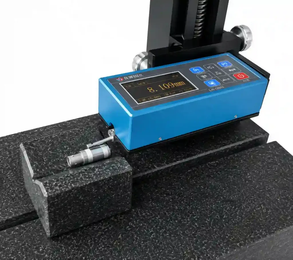
Interrupted surfaces and thin sections
Correlate the finish map with changes in engagement and workpiece stiffness. Crossing a hole or pocket changes the cutting event, while a thin flange can move under cutting or clamping. The same nominal face can therefore contain several local machining conditions.
Review support beneath the affected region and the position of clamps. A plate forced flat during machining can recover after release, changing the apparent pass relationship. Adding clamp force may improve contact while increasing that deformation, so evaluate the complete force path.
Chip recutting can create localized scratches or torn areas. Inspect evacuation and the surface at the relevant interruption rather than assuming that every defect has the same periodic cause as the feed marks nearby.
The ASME drawing framework distinguishes geometric requirements that should remain explicit when assessing the result. A texture correction does not establish flatness or parallelism. For a flexible face, identify whether acceptance is free state or a defined restrained condition. Keep that condition consistent when comparing trial passes, otherwise movement introduced by handling can be mistaken for a cutting improvement.
Verify the correction with a test pass
Change a variable that tests the diagnosed mechanism. If an insert is suspected, confirm the assembled edge condition before the pass. If local support is implicated, preserve the rest of the cutting condition while assessing the support change. A collection of simultaneous adjustments yields a weak explanation even when the next face looks better.
Use a representative face and sufficient stock for a meaningful trial. A very light cosmetic pass may interact differently with the edge than the planned finishing cut. Confirm the permissible trial region before machining a feature that has little remaining allowance.
Record the original and revised condition, including the tool assembly, path and part restraint. Compare the same locations and measurement direction after the cut. Preserve both the successful and unsuccessful observations so the next operator understands the reason for the approved change.
For a multi-orientation route using 5-axis machining, identify the orientation and setup where the symptom occurred. Approval of a correction on one face does not demonstrate every orientation and engagement condition in the part.
Feed units, spindle settings and tool identities
Confirm the parameter meanings before interpreting mark spacing. Feed per tooth, feed per revolution and table feed describe different quantities. A correct numerical value entered under the wrong unit or mode can invalidate the comparison with the intended cutting condition.
Sandvik Coromant’s milling formulas and definitions relates table feed to spindle speed, effective tooth count and feed per tooth. Use that relationship with the actual tool configuration, not a pocket count assumed from the cutter’s appearance.
| Input | Meaning to confirm | Diagnostic consequence |
|---|---|---|
| Feed | Units and programmed mode | Expected spacing and cutting load |
| Spindle speed | Actual applied speed | Rotation-related pattern spacing |
| Effective teeth | Edges participating in the cut | Feed-per-tooth interpretation |
| Tool assembly | Body, inserts and holder revision | Runout and surface-generation condition |
If a controller-mode question remains, consult the exact machine documentation before editing the program. A diagnostic calculation is useful only when its inputs represent the condition the machine actually executed.
A mark-spacing calculation with defined assumptions
Consider a hypothetical face-milling trial with a table feed of 600 mm/min, spindle speed of 1000 revolutions/min and four effectively cutting teeth. These are illustrative inputs, not recommended cutting data for a material or tool.
The calculated feed per revolution is 600/1000 = 0.6 mm/revolution. Dividing by four gives 0.15 mm/tooth. If one edge dominates surface generation because of the actual tool geometry or axial position, a once-per-revolution feature may be more relevant to a visible pattern than simply assuming four equal marks per turn.
This calculation helps frame observations; it does not prove a cause from a photograph. Tool-path overlap, wiper geometry, vibration and measurement direction can produce different spatial features. Compare a measured pattern with the actual setup and use a controlled trial to distinguish explanations.
Mitutoyo’s surface-texture measurement guide explains measurement conditions and texture parameters. Choose the appropriate evaluation direction and settings for the specified requirement. A trace across the wrong direction or a short region selected for appearance can obscure the pattern that the calculation was intended to investigate.
First-part checks after the corrective pass
Verify the corrected surface against the actual acceptance requirements. Inspect texture at defined locations and evaluate geometry independently where flatness, step height or interface relationship matters. A visually improved face may still contain an unacceptable pass junction.
Compare the part after the required release from workholding. If final acceptance is in free state, a measurement made while the plate remains clamped provides intermediate process evidence. Record that distinction rather than combining the two conditions in one report.
Inspect the tool after the trial where edge damage or built-up material was part of the hypothesis. A good initial face may not represent the condition after the relevant machining interval. Establish the approved boundary using the product and process requirements.
NIST’s uncertainty-analysis guidance connects measurement quality with fitness for a decision. Apply it when a small apparent roughness or step improvement drives acceptance. Keep the evaluation settings and locations in the report. The number of decimal places displayed cannot establish whether the method distinguishes the change or whether the selected trace represents the functional face.
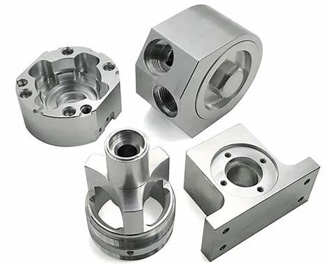
Surface evidence to retain in the process handoff
Retain a marked face image, toolpath orientation and the diagnosed mechanism with the approved setup. Include the assembled tool identity, relevant insert condition, restraint and parameters. This is more useful than a note saying reduce feed until acceptable, which loses both the reason and the accepted boundary.
Identify the inspection locations and conditions used to confirm the correction. If a different instrument or trace direction is proposed later, review whether its results are comparable before treating a changed reading as a process drift.
Separate maintenance actions from program revisions. A reseated insert, cleaned mounting surface or revised support can be essential to the result without appearing in the NC file. Preserve those requirements in the appropriate setup instructions.
The standards and tolerances reference can support drawing discussions. The actual surface and geometric limits must remain in the released product documents. For repeat work, keep any approved visual sample tied to measurable requirements so lighting and photographic appearance do not become the sole acceptance method.
FAQ
Can polishing resolve a face-milling finish complaint?
It can change surface appearance and texture, but it may also change edges, geometry or the evidence needed to diagnose the original marks. Review whether polishing is permitted and what final requirements still apply. Preserve the as-machined observations before any rework. If the complaint concerns a step, flatness or a damaged interface, a smoother appearance alone does not demonstrate that the underlying requirement has been restored.
Does a lower Ra value prove that chatter has stopped?
No. Ra summarizes one aspect of a measured profile under specified evaluation conditions. It does not uniquely identify vibration, and a local trace may miss a broader periodic pattern or a pass junction. Compare the surface map, process observation and appropriate geometry or texture measurements. Keep location, direction and settings consistent when evaluating a correction so an improved number is not merely the result of selecting another trace.
Should a finish correction be copied to another cutter diameter?
Review it first. Changing cutter diameter can alter engagement, surface generation, stiffness and the relationship between speed and the programmed feed. The earlier correction may have addressed a specific assembled tool condition rather than a general material response. Recalculate the relevant quantities and confirm the new tool arrangement using its manufacturer's guidance. Validate the resulting face instead of transferring a favorable setting solely because the insert grade is unchanged.
Conclusion
Read the face as evidence of a cutting event. Distinguish regular generated texture from pass geometry, edge damage, local movement and chip effects, then use a controlled pass to test the most plausible mechanism. A parameter change is valuable when it resolves the diagnosed problem and preserves the other product requirements.
Confirm the accepted result with defined texture and geometric checks after the required release stage. Retain the mechanical setup and tool condition alongside the program revision. This makes the correction reproducible instead of dependent on a visually successful trial whose cause was never established.
For a machining review, upload the part CAD, surface requirements and marked cutter-pattern photographs. Include the affected face and measurement conditions so 6CProto’s DFM review can assess the actual interface and finishing route.
{“@context”: “https://schema.org”, “@type”: “FAQPage”, “mainEntity”: [{“@type”: “Question”, “name”: “Can polishing resolve a face-milling finish complaint?”, “acceptedAnswer”: {“@type”: “Answer”, “text”: “It can change surface appearance and texture, but it may also change edges, geometry or the evidence needed to diagnose the original marks. Review whether polishing is permitted and what final requirements still apply. Preserve the as-machined observations before any rework. If the complaint concerns a step, flatness or a damaged interface, a smoother appearance alone does not demonstrate that the underlying requirement has been restored.”}}, {“@type”: “Question”, “name”: “Does a lower Ra value prove that chatter has stopped?”, “acceptedAnswer”: {“@type”: “Answer”, “text”: “No. Ra summarizes one aspect of a measured profile under specified evaluation conditions. It does not uniquely identify vibration, and a local trace may miss a broader periodic pattern or a pass junction. Compare the surface map, process observation and appropriate geometry or texture measurements. Keep location, direction and settings consistent when evaluating a correction so an improved number is not merely the result of selecting another trace.”}}, {“@type”: “Question”, “name”: “Should a finish correction be copied to another cutter diameter?”, “acceptedAnswer”: {“@type”: “Answer”, “text”: “Review it first. Changing cutter diameter can alter engagement, surface generation, stiffness and the relationship between speed and the programmed feed. The earlier correction may have addressed a specific assembled tool condition rather than a general material response. Recalculate the relevant quantities and confirm the new tool arrangement using its manufacturer’s guidance. Validate the resulting face instead of transferring a favorable setting solely because the insert grade is unchanged.”}}]}