

Explore CNC Programming & Process Engineering Guides
A stronger cutter corner can leave a radius that interferes with the mating part. A nominally square tool can meet the intended transition while exposing a vulnerable cutting edge. Selecting between them requires a clear picture of the material that may remain at the floor-wall junction and the operation that will remove it.
End mill corner radius vs square end selection is therefore a geometry and process decision together. Start with the finished part requirement, then choose the roughing and finishing tools that can produce it without relying on an assumed perfect corner.
Keep the tool’s corner radius separate from the pocket’s plan-view corner radius. The cutter diameter constrains one relationship, while the radius blending its end and periphery constrains another. Confusing them can produce a manufacturable-looking model with an unacceptable internal transition.
The CNC milling service supplies the manufacturing context. This guide focuses on edge strength, the remaining profile and finishing strategy. It does not rank cutter styles for every material or repeat a general comparison of face-milling processes.
Corner strength and cutting load
Choose the edge profile within the part’s limits.
A rounded cutter corner can reduce vulnerability at the edge, but its radius must remain compatible with the finished transition and the load imposed by the actual cutting strategy.
Harvey Performance’s corner-radius tooling guidance explains how rounding distributes cutting forces around the corner and can help reduce chipping. Its recommendation remains conditional on the part allowing the radius; it does not make every rounded cutter superior in every operation.
Review the material, engagement and tool reach with the chosen profile. A corner-radius tool carrying too much load or used with inadequate support can still fail. A square-end tool can remain appropriate when the geometry requires it and the finishing condition is controlled.
Distinguish roughing capability from final-feature capability. It may be sensible to protect the roughing edge with a radius and reserve a square-end tool for the limited remaining material. That route changes the finishing engagement, so the second tool must be evaluated against the stock it actually encounters rather than the nominal full pocket.

Floor to wall transitions
Read the floor-wall junction in section. A corner-radius end mill typically leaves a blended transition when its end and peripheral edges finish the adjacent surfaces in the corresponding orientation. If the drawing requires a sharper junction, the remaining material needs a defined finishing route.
Do not confuse this blend with a vertical internal corner in the pocket’s plan view. That corner is constrained by the cutter’s swept diameter and path. Reducing the tool corner radius does not make a large-diameter cutter produce a small plan-view corner.
The ASME drawing framework supports specifying the required profile and its relationship to adjacent surfaces. It does not assume that a CAD sharp edge means an achievable zero-radius physical corner. State the acceptable transition or other functional clearance explicitly.
Check the mating component’s envelope. A small fillet can interfere with a square shoulder even when the floor depth and wall position pass separately. A relief in one part may offer a better solution than forcing a vulnerable cutter to generate an unnecessarily sharp junction. Such a design change needs approval rather than an informal machining interpretation.
Stock allowance for a second operation
Define the remaining stock in the transition region, not only the allowance on the flat wall and floor. A radius used during roughing can leave a local wedge or band of material that the finishing tool meets abruptly. That engagement may be much greater than the nominal wall allowance suggests.
Review the stock model before selecting the second tool’s path. Where possible, make the finishing engagement deliberate and avoid an unplanned full-width encounter at a corner. The appropriate strategy depends on the feature and cutter rather than a universal reduction in feed.
Sandvik Coromant’s closed-pocket guidance gives a specific sequence separating wall machining from radius finishing for closed-angle features. Preserve that application context. It illustrates that different parts of an internal transition can justify separate tools without prescribing that exact route for every ordinary pocket.
For multi-axis machining, consider whether orientation improves access while maintaining the required profile. More axes do not eliminate tool-envelope constraints. Confirm holder clearance, remaining stock and the surfaces affected by the alternate approach before treating it as a complete finishing solution.
Inspect the remaining corner profile
Measure the transition that controls function. Separate floor depth, wall location, blend radius and any permitted relief. A caliper measurement across the pocket cannot demonstrate the local floor-wall profile, even when its reading is repeatable.
Choose an inspection route with access to the feature. A contact probe has its own geometry and may not reach the smallest region directly. Optical methods also need a suitable view and an evaluation that corresponds to the drawing. Define the method before a hidden corner becomes the only unresolved acceptance item.
Renishaw’s metrology-fixturing overview emphasizes repeatable positioning for inspection. Use stable references while leaving access to the transition. A fixture that hides the junction can make otherwise convenient inspection evidence incomplete.
Check the finished mating condition where it is part of the agreed acceptance, but do not treat a fit demonstration as a substitute for every specified dimension. A mating part can contain its own clearance or variation. Retain the profile result and the functional observation as separate evidence so the reason for acceptance remains clear.

Tool radius, part radius and setup units
Keep tool geometry and product geometry in separate fields of the setup record. A drawing radius is a requirement; a cutter radius is an input to producing it. The nominal values may coincide in a simple strategy, but that equality should not be assumed for every orientation or finishing path.
Confirm units and tool-library identity before programming. A radius entered as a diameter or an imperial value interpreted as metric changes the modeled envelope even when the tool name looks familiar.
| Quantity | Meaning | Review point |
|---|---|---|
| Tool diameter | Swept peripheral envelope | Plan-view access and internal corner |
| Tool corner radius | End-to-periphery blend | Floor-wall transition |
| Part profile | Accepted delivered geometry | Drawing and inspection method |
| Remaining stock | Material before finishing | Local second-operation engagement |
Use the actual tool drawing and the selected CAM representation. Controller-specific compensation or mode questions require the exact machine documentation. A geometrically correct tool model does not justify an unverified program interpretation.
A hypothetical transition and mating-clearance review
Consider a hypothetical pocket roughed with a tool having a 1 mm corner radius. The product drawing permits a floor-wall blend no larger than 0.3 mm in a defined mating region. The roughing tool cannot establish that accepted transition simply by reaching the nominal floor and wall coordinates.
The second operation must remove the remaining material in that region with a tool and path capable of producing the permitted profile. A smaller-radius or square-end tool is one possible proposal; a deliberately designed relief is another if the product authority approves it. These are alternatives to evaluate, not interchangeable automatic fixes.
Check the remaining-stock model in section. The local material is not necessarily represented by a uniform wall offset. Simulate the proposed path with the holder and nearby features included, then inspect a representative first part.
Autodesk’s fillet and chamfer documentation describes these as distinct modeling operations. Use that distinction when reviewing a revised CAD transition: substituting a chamfer for a fillet changes the delivered geometry and needs the corresponding drawing and mating-clearance review.
Simulation and first-part transition checks
Simulation should test the proposed tool envelope and stock-removal sequence. Include the actual corner geometry and the remaining material from earlier operations. A collision-free centerline path is insufficient if the cutter leaves an unacceptable blend or engages an unexpected stock band.
Verify the first part at the critical transition and adjacent surfaces. Check whether the tool leaves a step, relief, witness or local damage that the drawing does not permit. Inspect the relevant edge condition after the cut when chipping resistance was part of the tool-selection decision.
Preserve the part’s inspection state and the measurement references. If a later finishing process changes the corner, establish acceptance after that process as well. A passed intermediate profile is not final evidence for a different delivered condition.
NIST’s uncertainty-analysis guidance connects measurement quality with decision fitness. Apply that reasoning when the allowed blend is small relative to probe access or method variation. Do not report a more precise radius than the available evidence can establish. Resolve the inspection limitation before using the first part to approve the repeat route.
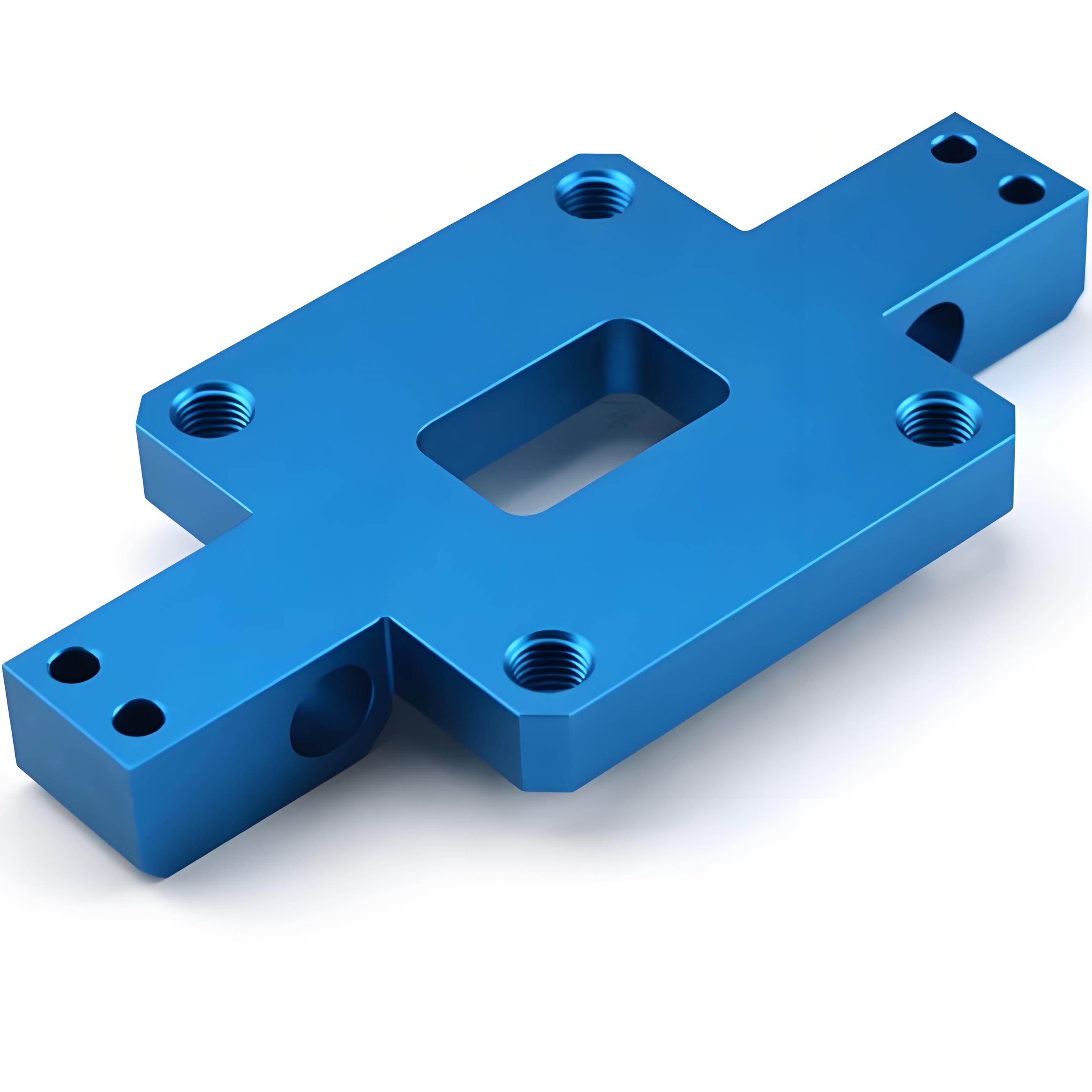
Corner-profile requirements in the machining handoff
Retain the accepted profile, tool identities and finishing sequence with the setup documentation. State which tool generates the final transition and which tool only removes bulk stock. That avoids a later substitution that preserves cutter diameter while changing the corner left in the part.
Identify the inspection locations and any functional mating region. A broad note allowing a radius everywhere may unintentionally relax a critical shoulder, while a global sharp-corner requirement can impose unnecessary difficulty on nonfunctional areas.
Record approved design changes such as reliefs or revised blends in the controlled product documents. A shop sketch can explain a proposal, but it should not become the sole authority for changing the delivered geometry. Preserve the acceptance evidence for the revised feature.
The standards and tolerances reference can support that discussion. The drawing and agreed inspection method must establish the actual corner limits. For repeat orders, review changes to reach, holder, tool profile or earlier stock-removal operations against the local finishing engagement rather than only the final pocket dimensions.
FAQ
Does a square-end mill produce a mathematically sharp internal corner?
Do not assume it does. The actual edge preparation, tool condition and process can leave a finite transition, and a vertical plan-view corner remains constrained by the cutter's swept diameter. Define the physical requirement that matters to the mating part. If an especially sharp junction or local relief is necessary, review a suitable manufacturing and inspection route rather than relying on the tool category name as acceptance evidence.
Can the finishing cutter have the same diameter as the roughing cutter?
Possibly, if its profile, reach and path can remove the remaining transition material without violating the part envelope. Diameter alone does not establish that capability. Compare the actual tool sections and the stock left by roughing. Evaluate local engagement and clearance, then verify the resulting profile on the first part. A matching diameter can simplify one aspect of the setup while leaving the floor-wall geometry question unresolved.
When is a relief preferable to demanding a smaller blend?
A relief can be useful when it provides the required mating clearance with a more practical tool and inspection route. Its suitability depends on the local load path, remaining section, sealing or contact requirements and available space. Obtain design approval and update the controlled geometry. Do not add a relief simply to hide an unmachined fillet, because the alternative removes material and can affect functions beyond the original interference.
Conclusion
Select the cutter profile around the transition the part must retain. A rounded edge can protect the tool, while a sharper finishing profile can address a restricted junction; a combined route can serve both when its remaining stock is understood. Keep those decisions tied to the actual geometry and cutting condition.
Inspect the local profile separately from pocket depth and width. Record the accepted tool and finishing strategy so a later cutter substitution does not quietly change the mating interface. Where a relief offers a better solution, approve it as a product change and verify its consequences.
For a machining assessment, upload the pocket CAD, permitted transition and mating-clearance requirements. Include the critical section so 6CProto’s DFM review can evaluate the tool envelope and finishing route against a defined interface.
{“@context”: “https://schema.org”, “@type”: “FAQPage”, “mainEntity”: [{“@type”: “Question”, “name”: “Does a square-end mill produce a mathematically sharp internal corner?”, “acceptedAnswer”: {“@type”: “Answer”, “text”: “Do not assume it does. The actual edge preparation, tool condition and process can leave a finite transition, and a vertical plan-view corner remains constrained by the cutter’s swept diameter. Define the physical requirement that matters to the mating part. If an especially sharp junction or local relief is necessary, review a suitable manufacturing and inspection route rather than relying on the tool category name as acceptance evidence.”}}, {“@type”: “Question”, “name”: “Can the finishing cutter have the same diameter as the roughing cutter?”, “acceptedAnswer”: {“@type”: “Answer”, “text”: “Possibly, if its profile, reach and path can remove the remaining transition material without violating the part envelope. Diameter alone does not establish that capability. Compare the actual tool sections and the stock left by roughing. Evaluate local engagement and clearance, then verify the resulting profile on the first part. A matching diameter can simplify one aspect of the setup while leaving the floor-wall geometry question unresolved.”}}, {“@type”: “Question”, “name”: “When is a relief preferable to demanding a smaller blend?”, “acceptedAnswer”: {“@type”: “Answer”, “text”: “A relief can be useful when it provides the required mating clearance with a more practical tool and inspection route. Its suitability depends on the local load path, remaining section, sealing or contact requirements and available space. Obtain design approval and update the controlled geometry. Do not add a relief simply to hide an unmachined fillet, because the alternative removes material and can affect functions beyond the original interference.”}}]}