

Explore CNC Programming & Process Engineering Guides
A mating tab can fail to enter a wire cut opening even when the straight walls measure correctly. The interference sits in the corner, where a nominal radius has been treated as a guaranteed finished profile. Wire EDM minimum inside radius needs a geometry allowance, an achievable process and an inspection method capable of seeing the actual transition.
The wire diameter is only the starting point. Material removal occurs across a discharge gap, and the wire must change direction while the cut evolves through the workpiece thickness. A machine’s ability to use a fine wire does not by itself establish the corner form, local surface condition or dimensional accuracy of the requested feature.
For a procurement or design review, establish what the corner must do. Clearance for a mating part, a cutting edge and a stressed internal transition require different acceptance boundaries. State the permissible radius or profile and its location through the thickness, then ask for evidence on the relevant material and section. This keeps a useful geometric estimate from becoming an unsupported manufacturing promise.
Separate wire radius from finished radius
Wire radius is half the nominal wire diameter. The finished internal corner also reflects the effective discharge gap and the process used to generate the transition. As a first geometric estimate, R is approximately d/2 + g, where d is wire diameter and g is the relevant radial gap. It is not a guaranteed minimum on an arbitrary machine.
The Reliable EDM handbook explains that the cut extends beyond the wire and distinguishes internal from external corners. Use that mechanism rather than copying a catalog radius that may apply to another wire, pass condition or material. Confirm the units and whether a quoted allowance is radial or diametral before using it.
For a hypothetical wire diameter of 0.20 mm and assumed finishing gap of 0.01 mm, the estimate is 0.11 mm. Both inputs are illustrative. A design requiring less must prompt a process review, not a silent reduction in the assumed gap until the arithmetic agrees with the drawing.
State whether any published gap allowance is radial or diametral; using the wrong convention changes both the estimated corner and the expected kerf.
Spark gap and corner overburn
A straight cut offset does not fully describe the local behavior as the wire turns. Discharge conditions, wire motion and debris can affect material removal around the corner. The finished result may depart from a simple circular arc even when its fitted radius looks acceptable.
Mitsubishi Electric’s corner control discussion describes control based on corner geometry and speed, and distinguishes dimensional acceptance from a customer’s microscopic surface concerns. That example belongs to the manufacturer’s equipment; it does not establish a capability for every EDM installation. It does demonstrate why a radius number and a satisfactory local surface are separate requirements.
Ask the specialist to identify the relevant control and pass strategy for the feature. Keep any corner compensation linked to the workpiece thickness and actual material. An adjustment that improves one profile at the top surface may not establish the shape midway through the cut. Inspect the required section rather than assuming the visible edge describes the entire wall.
Where the transition joins two controlled walls, retain the adjoining straight segments in the report so alignment does not absorb a local corner error.
Tight radius versus accuracy trade offs
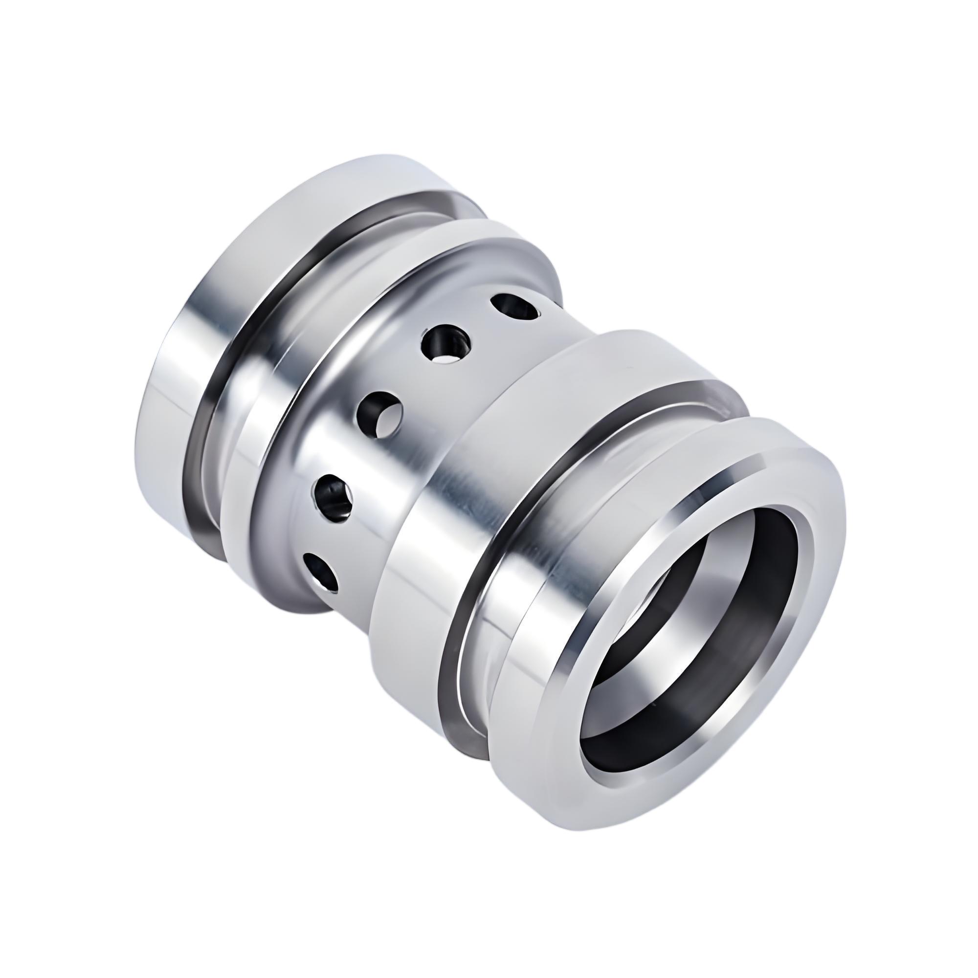
A smaller wire can provide geometric access to a tighter corner, but the whole cut still needs stable operation and acceptable form. Compare the required profile with the consequences for machining time, wire handling and trial evidence. Do not describe the smallest available wire as the automatically most accurate choice.
Give the manufacturing team freedom where function permits it. A corner relief or a slightly larger internal transition may allow the mating feature to clear without requiring a tighter manufacturing limit. Such changes need design approval because they alter the product geometry, stress distribution or available material.
The economics should be tied to the actual acceptance condition. Additional finish passes may improve an identified characteristic, but a fixed pass count is not a substitute for a result. For an EDM feature review, separate the minimum permissible corner from the profile tolerance on adjacent walls. This prevents an unnecessarily small radius from controlling a much larger and otherwise straightforward opening.
If clearance permits, compare a deliberately relieved mating corner with a smaller radius requirement before committing the whole profile to finer wire.
Inspect the actual corner profile
Measure the corner transition itself, including the tangency region and the sections required through the thickness. A best fit circle can hide a local protrusion or an undercut if the selected data cover only part of the transition. Agree the point selection and reporting method before comparing results.
For a clearance feature, a controlled mating profile or functional gauge may be valuable alongside dimensional inspection. It should represent the limiting assembly condition and must not replace unrelated geometric requirements. A passing gauge shows that defined relationship, not a complete map of the surface.
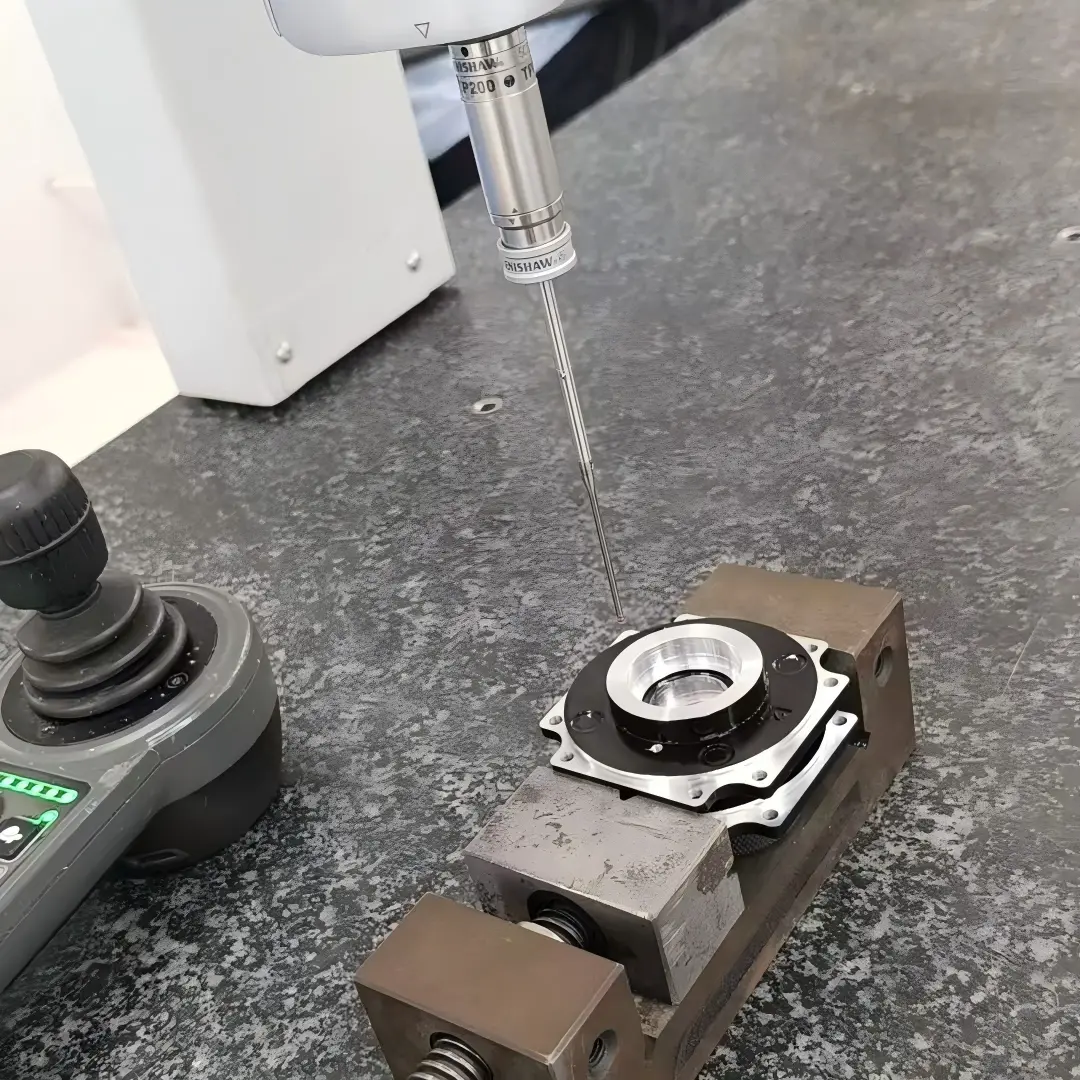
Use repeatable support and a known reference alignment. Renishaw’s metrology fixturing information describes setups intended to improve reproducibility. If optical methods inspect the top edge, state that scope and establish how mid thickness form is addressed when relevant. A clear image at one surface cannot establish that the complete cut has the same corner geometry or that no local taper exists.
Report the fitted region as well as the numerical result, especially when different inspectors might select different portions of a noncircular transition.
Map wire entry, cut height and slug access
A wire cut feature needs an accessible wire route through the workpiece. Identify the starting access, lead in, final profile and how the separated slug will be managed. The inspection references must survive the sequence so the corner remains related to the component’s functional geometry.
Show thickness changes, interrupted surfaces and obstructions near the flushing nozzles. A profile that appears simple in plan view may present different discharge conditions along its height. Include these conditions in the section supplied for review, rather than sending only a two dimensional outline.
If the component also requires turning operations, define which surfaces establish the EDM and inspection setup and when they are finished. Record any finishing operation after EDM that can change the corner or edge. A polishing or deburring instruction should have an explicit allowance when the smallest transition controls assembly. Otherwise, a satisfactory cut can be altered after its nominal process has already passed.
Locate the lead in away from a critical contact zone where possible, and identify how any associated witness condition will be accepted.
Verify corner profile, wall alignment and surface texture
Separate local corner form, wall location and surface texture in the verification plan. These characteristics interact in use but require different evidence. State the measured section, alignment and evaluation rule with each result so the reported radius remains interpretable.
| Characteristic | Evidence | Limit to avoid |
|---|---|---|
| Inside transition | Profile data and defined fit or envelope | One fitted radius hiding local error |
| Wall relationship | Location and orientation from datums | Corner inspection without alignment |
| Through thickness form | Specified sections or qualified alternative | Top view assumed to represent all heights |
| Surface texture | Specified parameter and measurement conditions | Visual smoothness treated as a number |
Mitutoyo’s surface texture guide distinguishes measured profiles, filtering and roughness parameters. Use the applicable parameter and access conditions; a radius image does not establish a roughness result. Keep both requirements visible when the corner is a functional contact or cutting feature.
Qualify the corner at the required material and thickness
Choose a trial feature that reproduces the requested radius, material, thickness and nearby geometry. A thin demonstration coupon does not establish a tall wall with interrupted flushing. Identify any difference between the trial and production component before using its results for approval.
Record wire designation, pass sequence and the inspected locations with the profile report. The buyer need not prescribe the supplier’s entire machine program, but the accepted process should be traceable enough to evaluate later changes. Retain representative parts when a local edge or surface condition matters beyond a numerical fit.
Use the drawing language consistently. The public scope of ASME Y14.5 covers communicating geometric requirements, while the actual tolerance and inspection agreement remain application specific. Define the boundary through the inspection requirements. Approval of one trial proves the tested configuration; a change in thickness, material or finishing route can require renewed evidence for the critical corner.
If a trial coupon omits a thickness step or interrupted flushing condition, treat that omission as a specific qualification limit requiring further evidence.
Corner limits and measurement heights for an EDM quote
The RFQ should include the conductive material and condition, thickness map, profile file, internal corner requirement and all adjacent wall tolerances. Identify whether the radius is nominal, a maximum for mating clearance or part of a controlled profile envelope. Those meanings lead to different acceptance decisions.
State the functional reason for the tight corner and any permitted relief. Include the available start location, access restrictions and surfaces that cannot be marked or altered. If a blind cavity is involved, flag it explicitly so it is not treated as an ordinary through wire profile.
Request the proposed verification scope along with the machining approach. Resolve optical access, measurement heights and any destructive trial before release. A specialist quotation that identifies an unverified mid thickness corner is more useful than an unrestricted minimum radius claim. Keep all accepted alternatives on the released revision so the supplier is not asked to reproduce a fine wire trial under a different geometry or finishing condition.
FAQ
Is the minimum inside radius exactly half the wire diameter?
That describes the wire radius, not the complete material removal envelope. An effective discharge gap also contributes, and the corner control and finish sequence influence the actual transition. Use the geometric estimate to identify whether a design needs specialist review, then qualify the finished corner on the relevant material and thickness. Do not reduce the assumed gap to make a desired radius appear feasible without supporting process evidence.
Can a top view prove the corner is acceptable through the plate?
It establishes only the visible section under the selected measurement method. Through thickness form can require additional sections or another qualified inspection approach. State where the radius and profile must meet the requirement, and identify the datum alignment used for comparison. If the function depends on full height clearance, a controlled mating gauge may add useful evidence, but it still should not replace unrelated dimensional or surface requirements.
Is a corner relief an acceptable substitute for a smaller wire?
It may solve a clearance problem if the design allows the added material removal. Evaluate its effect on the surrounding wall, loading, sealing and assembly before approval. Define the relief geometry on the drawing and inspect it as part of the released feature. A manufacturing suggestion to add relief is a product change, so a supplier should not apply it silently merely because the original corner is difficult to produce.
Conclusion
Specify the corner as a finished functional boundary. Wire size and a gap estimate help assess feasibility, but the accepted transition also needs an appropriate cut strategy and observable evidence through the required thickness. Keep radius, adjacent wall geometry and local surface condition as distinct acceptance items.
Use trial results to approve the relevant configuration, and preserve the conditions that made them representative. When a smaller wire or a relief is proposed, compare it against the actual mating requirement before changing the drawing. For a review with 6CProto, send the profile, thickness sections and corner acceptance boundary for quotation. A precise functional requirement gives the specialist room to propose an economical process while keeping the critical geometry under control.
{“@context”: “https://schema.org”, “@type”: “FAQPage”, “mainEntity”: [{“@type”: “Question”, “name”: “Is the minimum inside radius exactly half the wire diameter?”, “acceptedAnswer”: {“@type”: “Answer”, “text”: “That describes the wire radius, not the complete material removal envelope. An effective discharge gap also contributes, and the corner control and finish sequence influence the actual transition. Use the geometric estimate to identify whether a design needs specialist review, then qualify the finished corner on the relevant material and thickness. Do not reduce the assumed gap to make a desired radius appear feasible without supporting process evidence.”}}, {“@type”: “Question”, “name”: “Can a top view prove the corner is acceptable through the plate?”, “acceptedAnswer”: {“@type”: “Answer”, “text”: “It establishes only the visible section under the selected measurement method. Through thickness form can require additional sections or another qualified inspection approach. State where the radius and profile must meet the requirement, and identify the datum alignment used for comparison. If the function depends on full height clearance, a controlled mating gauge may add useful evidence, but it still should not replace unrelated dimensional or surface requirements.”}}, {“@type”: “Question”, “name”: “Is a corner relief an acceptable substitute for a smaller wire?”, “acceptedAnswer”: {“@type”: “Answer”, “text”: “It may solve a clearance problem if the design allows the added material removal. Evaluate its effect on the surrounding wall, loading, sealing and assembly before approval. Define the relief geometry on the drawing and inspect it as part of the released feature. A manufacturing suggestion to add relief is a product change, so a supplier should not apply it silently merely because the original corner is difficult to produce.”}}]}