

Explore CNC Cost, Tolerances & Supplier Selection
A T-slot section can be easy to draw and impossible to machine with the selected cutter because the head has no route into the undercut. A different design can admit the tool but leave too little neck clearance for a stable cut. These constraints should be resolved before the slot becomes a fixed assembly interface.
T slot machining design needs a continuous path for the complete cutting assembly, followed by a credible route for inspection. The visible opening and the hidden bearing faces impose different requirements. A nominal slot width alone cannot define either manufacturing access or the way the mating component carries load.
This guide focuses on the undercut’s entry, retained material and accepted geometry. It does not provide a general feed table or assume that a standard cutter exists for every drawn section. Tool availability and the actual machine setup belong in the part-specific review.
Include the mating nut, slider or captured component in the CNC-milling review. Its assembly route may need the same entry opening as the cutter, or a separate opening with different requirements. Keep both paths visible so a tool-access solution does not create an unusable product interface.
Where does the cutter enter a T slot machining design?
Provide a continuous route into the undercut.
An open end or approved entry pocket must admit the cutter head and allow withdrawal, while preserving the bearing faces and remaining material required by the assembled interface.
Trace entry, cutting travel and exit on the complete model. An open-ended slot can admit a head laterally, while an enclosed slot may need a larger local access opening or another manufacturing route. A neck-sized opening does not allow a larger head to pass vertically through solid material.
Sandvik Coromant's groove-and-slot guidance distinguishes open and closed slots and relates cutter choice to width, depth and available setup. Those distinctions should precede the selection of a particular T-slot tool.
Check what remains after the entry feature is added. A larger access pocket can shorten the useful bearing length or interrupt the load path. Identify any assembly restriction near that pocket and include the required travel stop. A manufacturable cutter entry is useful only when the finished slot still retains and locates its mating component as intended.
Cutter head and neck clearance
Check the cutter head diameter and thickness, neck diameter and reach, shank and holder against the intended path. The head must reach the hidden faces while the neck clears the upper opening. The rest of the assembly must clear the surrounding part and fixture.
Harvey Performance's undercutting-tool guidance explains the clearance and rigidity trade-off of reduced-neck tools. Its spherical undercutters are not a substitute for every T-slot cutter, but the underlying lesson applies: extra neck clearance is purchased with a change in tool stiffness and usable cutting conditions.
Compare the actual tool drawing or model with the slot’s tolerance extremes. Nominal clearance can disappear when the opening is at its minimum width or when the tool assembly deflects under the chosen operation. Do not use a zero-clearance CAD fit as a production proposal.
Identify whether one tool can finish both bearing faces or whether another pass is required. Tool changes and overhang can affect relative face position, corner form and surface quality. Record these consequences before choosing a profile that depends on an unusually long or narrow neck.
Slot width and depth tolerances
Separate the upper opening, undercut width, undercut height and the position of the hidden bearing faces. Each can control a different part of the assembly. A single overall section dimension can leave the functional clearance or retained lip thickness undefined.
Identify the surface that carries the service load and dimension it relative to the required datum. The mating component may need running clearance in one direction and controlled contact in another. Review those relationships rather than tightening every slot dimension equally.
The ASME Y14.5 scope provides the framework for communicating dimensioning and tolerancing. The actual drawing must select the relevant size, orientation and location requirements; citing a standard does not determine them automatically.
Specify the final state when a coating or finishing operation changes the fit. Include permitted corner radii and edge conditions where they affect seating. A mathematically sharp internal corner may not match the tool geometry, and an uncontrolled edge break can reduce the bearing area the assembly depends on.
Measure the hidden bearing faces
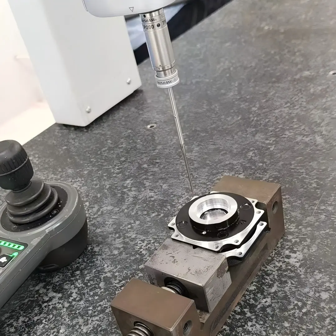
Plan how the inspector will contact or observe the load-bearing surfaces after machining. The cutter’s ability to reach a face does not establish probe access. A measurement tip can fit in the cavity while its stem or the probe body interferes with the opening.
Renishaw's stylus application guidance emphasizes practical reach, stiffness and suitable ball size. Apply those principles to a proposed stylus assembly, including the entry and withdrawal paths. A long extension selected only for reach can create an uncertain measurement.
Define whether the acceptance task is face position, parallelism, undercut width, clearance or local profile. These may require different contacts and sampling regions. A go/no-go slider can verify a defined assembly envelope but may not reveal which individual face is out of position.
Preserve the required datum setup. If the hidden faces need another orientation or fixture, define how the result relates to the original references. Do not replace an inaccessible drawing datum with a convenient clamp location without an approved measurement method.
A section view that exposes access and retained material
A useful section should show the cutter entry, the neck corridor, the undercut’s finished envelope and the remaining lips. Add the mating component’s envelope where it helps establish clearance and bearing contact. Keep illustrative tool geometry separate from product dimensions.
Consider a hypothetical access check with an 8 mm minimum upper opening and a proposed 6 mm neck. The nominal diametral difference at that section is 2 mm, or 1 mm per side when centered. That arithmetic describes geometric space only; it is not an approved machining margin or a stiffness assessment.
If the cutter head is wider than the upper opening, the drawing still needs an entry route that admits that head. The neck clearance calculation does not resolve the missing route. Likewise, holder clearance and usable neck length remain separate checks.
Mark the minimum retained lip and any local interruption created by the entry pocket. Review the actual load path with the product engineer before reducing material for tool access. The section should expose these competing requirements rather than imply that a positive neck clearance proves the entire design is ready.
Comparing cutting and verification routes
Select the route by access, geometry and required evidence. A dedicated T-slot cutter, a suitable undercutting strategy and a redesigned assembled feature can address different situations, but none should be approved from its process name alone.
The following comparison identifies the questions that need resolution. It does not assign universal capabilities or costs to the processes.
| Route | Access question | Acceptance question |
|---|---|---|
| Profiled slot cutter | Can the complete head enter and travel? | Does the tool profile produce both bearing faces? |
| Local undercutting passes | Can neck and holder clear each path? | Are corner form and face relationships controlled? |
| Separate retained component | Can the interface be assembled? | Does the additional joint preserve function? |
For inspection, compare direct dimensional measurement with a functional gauge against the requirement each can prove. A mating test is useful evidence of fit for that pairing, while a dimensional method can investigate the faces independently. Agree which evidence releases the slot and which supports troubleshooting.
Functional checks after undercut machining
Inspect the slot after the approved deburring and finishing route. Hidden burrs can obstruct a slider, while excessive edge removal can reduce bearing contact or change the captured component’s position. Neither is fully described by an opening-width measurement.
Check travel over the useful length and inspect the regions near entry pockets, ends and changes in direction. Include the required assembly load or contact condition where the product specification calls for it. A slider that moves freely when unloaded may bind when the retained surfaces carry load.
Review how the part is held during these checks. Renishaw's metrology-fixturing information addresses repeatable inspection setups; a particular T-slot still needs supports that expose its datums and avoid distorting thin lips.
Record the location and sign of any deviation. A single pass/fail label for the whole slot can hide a local high point or incomplete cut. Keep surface texture, geometry, burr condition and functional travel as separate observations so a corrective action addresses the actual cause rather than widening the entire slot unnecessarily.
Drawing questions to settle before quotation
Resolve the cutter entry and exit, required working length, bearing surfaces, corner form and final-state dimensions. Supply the mating-part geometry or its controlled interface dimensions. State whether the opening can be enlarged locally or the slot can run out through an edge.
Identify the required inspection evidence and any restricted probe access. The standards and tolerances reference supports the discussion, but the drawing and measurement agreement must define the actual feature’s acceptance.
If the slot belongs to a primarily rotational component, explain how its location relates to features made through the turning route. Datum transfer between operations can matter to the final interface even when the slot section itself is straightforward.
Retain the approved access assumptions in change control. A nearby wall or revised end stop can invalidate the original tool path without changing the nominal T-section. Review those dependencies when the component evolves, rather than discovering after machining that the original cutter or measurement route can no longer reach the hidden faces.
FAQ
Can a closed T-slot be made without any enlarged entry opening?
Possibly, using another justified process route, tool orientation or assembled construction, but the complete manufacturing path must be demonstrated. A conventional larger-head cutter cannot simply pass through a smaller opening into solid material. Ask the supplier to show the proposed tool assembly and path rather than assuming that an undercut label guarantees access. Evaluate the alternative against corner geometry, surface requirements, retained material and inspection needs before approving the design.
Does a mating slider qualify the slot dimensions?
It verifies the defined functional pairing under the conditions of that test. It does not automatically identify each bearing face's size, location or orientation, and another slider at a different tolerance extreme may behave differently. Use a controlled gauge or representative mating envelope where functional acceptance is intended. Keep individual dimensional checks where the drawing requires them. Define loading, travel range and allowable play so the assembly test produces a reproducible result.
Should every internal corner be relieved for the cutter?
Only where the product function and strength review permit it. Relief can improve tool access or allow a mating corner to seat, but it also removes material and can change contact or stress distribution. Identify the permitted relief envelope and inspect it in the final state. A supplier should not add an unrestricted pocket merely because it simplifies the toolpath. Review the mating geometry and load path before approving the local change.
Conclusion
A T-slot is ready for manufacture when its head entry, neck corridor and retained bearing geometry work as one complete design. Add an inspection route that reaches the same functional faces and preserves the required datums. Positive nominal clearance alone does not establish stable machining or acceptable assembly behavior.
Send 6CProto the model and drawing for a quotation, with mating geometry, useful travel, load-bearing faces and any permitted entry-pocket changes marked. Include the required dimensional and functional evidence so the proposed route addresses the complete slot interface.
{“@context”: “https://schema.org”, “@type”: “FAQPage”, “mainEntity”: [{“@type”: “Question”, “name”: “Can a closed T-slot be made without any enlarged entry opening?”, “acceptedAnswer”: {“@type”: “Answer”, “text”: “Possibly, using another justified process route, tool orientation or assembled construction, but the complete manufacturing path must be demonstrated. A conventional larger-head cutter cannot simply pass through a smaller opening into solid material. Ask the supplier to show the proposed tool assembly and path rather than assuming that an undercut label guarantees access. Evaluate the alternative against corner geometry, surface requirements, retained material and inspection needs before approving the design.”}}, {“@type”: “Question”, “name”: “Does a mating slider qualify the slot dimensions?”, “acceptedAnswer”: {“@type”: “Answer”, “text”: “It verifies the defined functional pairing under the conditions of that test. It does not automatically identify each bearing face’s size, location or orientation, and another slider at a different tolerance extreme may behave differently. Use a controlled gauge or representative mating envelope where functional acceptance is intended. Keep individual dimensional checks where the drawing requires them. Define loading, travel range and allowable play so the assembly test produces a reproducible result.”}}, {“@type”: “Question”, “name”: “Should every internal corner be relieved for the cutter?”, “acceptedAnswer”: {“@type”: “Answer”, “text”: “Only where the product function and strength review permit it. Relief can improve tool access or allow a mating corner to seat, but it also removes material and can change contact or stress distribution. Identify the permitted relief envelope and inspect it in the final state. A supplier should not add an unrestricted pocket merely because it simplifies the toolpath. Review the mating geometry and load path before approving the local change.”}}]}