

A thin prototype can remain dimensionally convincing while it is still attached to a surrounding frame, then move after the last tab is removed. Sacrificial features in CNC machining should therefore be designed with their removal in mind. Temporary support solves only the first half of the problem; the finished component must remain acceptable after that support disappears.
Tabs, extra stock, temporary bosses and surrounding frames can create useful workholding or stiffness. Their location should follow cutting forces, tool access and the final load path. Adding more bridges everywhere can obstruct machining and make the final finishing operation harder without improving the support that matters.
This guide focuses on prototype and small-batch release decisions. It does not prescribe universal tab dimensions or treat a CAM tab setting as a complete workholding design. Material, feature thickness, cutter engagement and the sequence of operations determine the required support.
The machining review should distinguish the finished product model from the manufacturing model that contains temporary material. That distinction lets the team plan removal, recover the correct datums and verify the released component without accidentally accepting a supported intermediate shape as the final part.
Where should sacrificial features in CNC machining carry load?
Temporary stock must support the actual cutting load path.
Place sacrificial features in CNC machining where they restrain the relevant movement, then assess cutter forces, remaining stiffness and release sequence rather than distributing tabs by appearance.
Identify the least rigid direction. A thin floor, tall wall and slender arm can need different support. A bridge placed near a convenient outer edge may contribute little to the local movement causing chatter or dimensional error.
Sandvik Coromant's vibration guidance relates cutting-force direction to tool, workpiece and fixture stability. Apply that principle to the temporary stock: connect the vulnerable region to a support capable of carrying the relevant force, while retaining access for the tool and chip evacuation.
Evaluate the changing condition through the sequence. A support adequate during roughing can become ineffective after surrounding stock is removed. Conversely, a heavy bridge that protects roughing may obstruct the final pass or require an awkward second setup.
Show the temporary geometry in the manufacturing model and define when it is removed. Avoid relying on an unrecorded decision to leave extra material. If the support is important enough to control deformation, it is important enough to appear in the route and verification plan.
Keep attachment marks away from functional surfaces
Tab locations should respect the final surfaces. A bridge on a sealing edge, bearing seat or cosmetic face can leave a witness that is difficult to remove without damaging a controlled feature. The removal tool also needs room beyond the nominal tab outline.
Locate support in regions with an acceptable finishing route and enough surrounding material for controlled cleanup. Where possible, separate the attachment from the tightest functional surface. If that cannot be done, plan a defined final machining operation rather than assuming that hand blending will recover the geometry.
Autodesk's tab reference describes control over tab shape, size and placement in a contour strategy. The software provides the geometry mechanism; engineering must still decide whether a selected tab location is suitable for the part and workholding arrangement. Automatic equal spacing is not a load-path analysis.
Review access from both sides. A bridge may be easy to cut from the roughing setup but inaccessible after the part is transferred to soft jaws. Check removal-tool clearance, remaining clamping space and protection of finished surfaces. A good location is one that can support machining and then disappear through a controlled operation without sacrificing the feature it was intended to protect.
Plan support removal and the final datum transfer
Support removal changes both stiffness and location strategy. Decide which surfaces locate the component during the final cleanup and which datum relationship must survive that transfer. A temporary boss can be a useful manufacturing datum, but its removal requires a deliberate move to the product’s functional datums.
Autodesk's manufacturing-model workflow distinguishes machining geometry from the source design. Use that separation to keep temporary features visible without changing the released finished part. The route should identify both models and their relationship.
Consider the order in which bridges are removed. The last connection may carry a different load from the first, and a loose component must remain securely controlled. Plan the physical release and handling method through the final cut. Machine guarding and approved workholding procedures still apply; Haas's safety documentation cautions against inadequately secured workpieces.
After release, allow the part to reach the agreed inspection condition before judging its dimensions. If movement occurs, distinguish residual-stress release from damage or forced deformation during cleanup. A documented sequence makes that investigation possible; an improvised removal operation can mix several causes and leave no useful evidence for the next build.
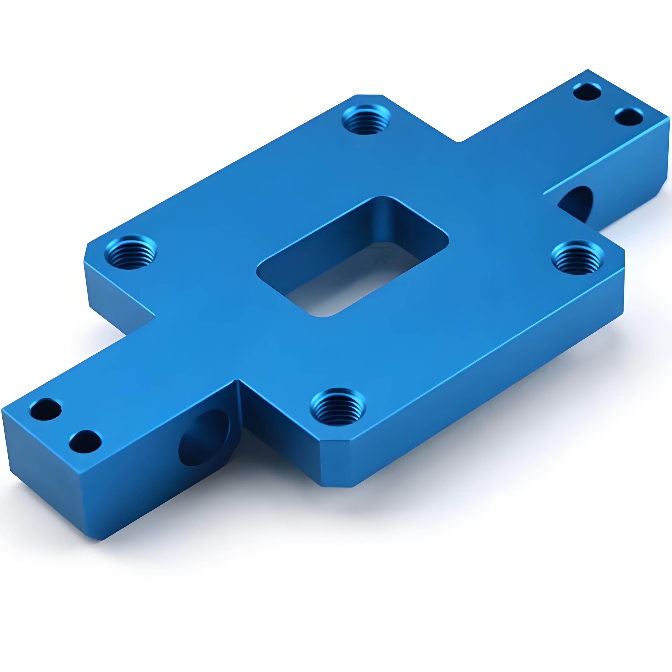
Inspect the component after temporary restraint disappears
The final inspection must occur after temporary material is removed and the cleanup is complete. Measurements made while a frame restrains the part are intermediate-process evidence. They can help diagnose movement but cannot replace acceptance in the required finished state.
Define how the part is supported for measurement. A thin component can be pushed into shape by a fixture or probe force. If the product operates in a constrained assembly, specify a representative support condition rather than assuming that either fully free or heavily clamped inspection is always correct.
Inspect the former attachment regions for dimensional loss, burrs and surface damage. Then measure the functional relationship that the temporary support was intended to preserve. A smooth-looking blended area does not prove that a nearby wall thickness or edge position remains within its limit.
The inspection agreement should distinguish supported, released and assembled states. Keep these states labeled in the record so that an apparently contradictory result can be interpreted. When a part moves after removal, comparing the before-and-after measurements can guide a revised stock-removal balance or support strategy without pretending that the original supported measurement established final conformity.
Compare tabs, bosses, skins and external fixtures
Temporary-stock choices should be compared through the complete route. A support that shortens roughing can still increase total work if it creates an inaccessible witness or requires a difficult datum transfer. The table below makes those consequences visible.
| Option | Useful role | Release risk | Decision evidence |
|---|---|---|---|
| Perimeter tabs | Retain a profile in surrounding stock | Local cleanup and final restraint | Removal access and released contour |
| Temporary boss | Create a clamping or locating interface | Datum transfer after boss removal | Final setup and functional datum check |
| Support floor or skin | Maintain stiffness during earlier operations | Movement when the layer is removed | Before-and-after wall or floor measurements |
| Dedicated fixture | Support the finished geometry externally | Clamping distortion or preparation effort | Unrestrained and supported inspection comparison |
Autodesk's thin-wall machining reference demonstrates that toolpath order itself can change support during material removal. Temporary stock is therefore one part of a broader sequence decision. Compare the required milling sequence with the support scheme rather than treating tabs as an independent afterthought added to a finished program.
Investigate a three-bridge prototype release sequence
Assume a hypothetical prototype bracket has a thin perimeter arm and two mounting bores that establish its functional location. The proposed manufacturing model leaves three bridges to an outer frame. The example tests the release strategy.
First machine and measure the mounting datums while the surrounding stock provides a stable reference. Record the arm position in the supported state. Next transfer the component using a fixture that locates on the intended datums without forcing the arm into position. Remove the bridges through a controlled sequence and finish the attachment regions.
Measure the arm again in the agreed final state. If it shifts, compare the direction and location of movement with the bridge layout and material-removal sequence. If only the attachment region is damaged, investigate cleanup access rather than redesigning every support. If the whole arm changes curvature, investigate stress release and stock-removal balance as well as restraint.
The decision gate is whether the released bracket meets its requirement with a reproducible route. A favorable supported measurement or an easy roughing cycle is not enough. Use the observed failure mechanism to change the next trial, retaining the unchanged measurement method for a useful comparison.
Retain evidence of the supported and released states
Prototype evidence should show which support arrangement and removal sequence produced the accepted part. Record material identity, manufacturing-model revision, setup transitions and the measured state. A photograph of the final component is useful context but does not explain the route that preserved its geometry.
Do not extrapolate a small trial into a universal tab rule. A different material, wall height or cutter engagement can alter the load path. Even a quantity increase can justify a different fixture or operation order, so repeatability must be evaluated for the selected route.
ASME's drawing framework helps distinguish the product’s controlled geometry from a manufacturing convenience. The final drawing should not accidentally require temporary stock to remain, while the manufacturing record should not lose the information needed to reproduce it.
When results are marginal, retain the actual deviations rather than only a pass summary. The movement after release can reveal whether the route is robust or depends on a favorable individual blank. Where a more demanding validation is required, define it from the component’s function and risk instead of claiming that one successful prototype establishes all future production behavior.
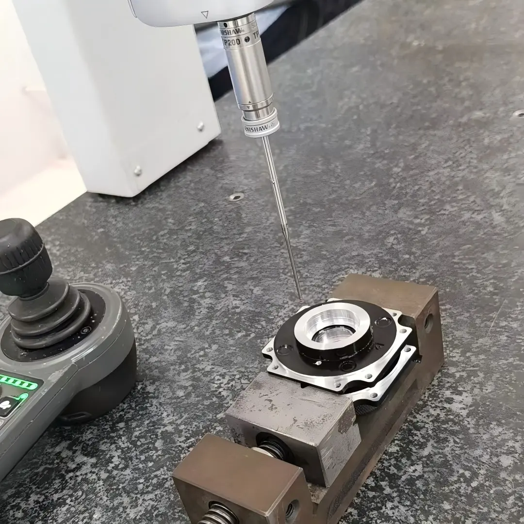
Hand over the final model and temporary-stock route
The handover package should preserve both the final model and the approved manufacturing model, clearly associated by revision. Mark temporary features, removal stages, datum transfers and surfaces needing final cleanup. Include the inspection state and the results that justified the route.
Define which changes require a new review. Moving a tab, changing a clamping face or removing a support earlier can affect a thin feature even when the finished CAD is unchanged. A process change should therefore be evaluated against the same functional requirement and released-state measurement.
For repeat orders, confirm whether dedicated fixtures or retained soft jaws replace part of the temporary-stock strategy. Do not assume that a prototype program will be reused unchanged or that a different fixture preserves the same deformation behavior.
The objective is a route that ends with the right part after every temporary feature has served its purpose. A clear release plan also reduces ambiguity at the supplier handoff: cleanup is part of manufacturing, not an undocumented operation left for the customer to complete before discovering whether the dimensions still agree.
FAQ
Can sacrificial tabs be broken off by hand?
That depends on the released removal method and the part's sensitivity. Breaking a tab can transfer load into a thin wall, leave an uncontrolled witness or damage a functional edge. It should not replace a planned cleanup operation simply because the connection looks small. Define how the component is restrained and what final geometry is required. Where hand removal is intentionally permitted, verify its consistency and inspect the affected region under the agreed criteria.
Should temporary stock appear on the customer-facing part drawing?
The finished product definition should remain unambiguous. Temporary geometry can be documented in a separate manufacturing model or process drawing linked to that definition. If customer approval is needed because the support affects a controlled surface or process restriction, show the relevant detail explicitly. Avoid placing unlabeled bridges on the final model, where they could be interpreted as product features or create confusion when the finished component is inspected.
Can the same support design be reused for a different alloy?
Not without reviewing stiffness, cutting behavior, residual stress and the removal operation. An identical bridge layout can behave differently when the material or stock condition changes. Start from the proven route as a candidate, then check the load path and released-state measurements on the new material. Keep the evidence associated with the actual alloy and condition rather than treating the support geometry as a universal fixture specification.
Conclusion
Sacrificial stock is successful only when the finished component remains correct after release. Place temporary material along the relevant cutting load path, keep attachment regions compatible with cleanup and preserve a workable datum strategy through the last operation.
The useful comparison is the complete route: support during machining, controlled removal, final finishing and inspection in the required state. If the part moves, use before-and-after evidence to distinguish stress release, inadequate restraint and cleanup damage. Those mechanisms lead to different corrections and should not be hidden by measuring a clamped intermediate shape.
For a thin or difficult prototype, share the finished model, critical surfaces and permitted temporary-stock regions with 6CProto. This supports a focused manufacturing review of tabs, support stock and the final inspection condition before the route is fixed.
{“@context”: “https://schema.org”, “@type”: “FAQPage”, “mainEntity”: [{“@type”: “Question”, “name”: “Can sacrificial tabs be broken off by hand?”, “acceptedAnswer”: {“@type”: “Answer”, “text”: “That depends on the released removal method and the part’s sensitivity. Breaking a tab can transfer load into a thin wall, leave an uncontrolled witness or damage a functional edge. It should not replace a planned cleanup operation simply because the connection looks small. Define how the component is restrained and what final geometry is required. Where hand removal is intentionally permitted, verify its consistency and inspect the affected region under the agreed criteria.”}}, {“@type”: “Question”, “name”: “Should temporary stock appear on the customer-facing part drawing?”, “acceptedAnswer”: {“@type”: “Answer”, “text”: “The finished product definition should remain unambiguous. Temporary geometry can be documented in a separate manufacturing model or process drawing linked to that definition. If customer approval is needed because the support affects a controlled surface or process restriction, show the relevant detail explicitly. Avoid placing unlabeled bridges on the final model, where they could be interpreted as product features or create confusion when the finished component is inspected.”}}, {“@type”: “Question”, “name”: “Can the same support design be reused for a different alloy?”, “acceptedAnswer”: {“@type”: “Answer”, “text”: “Not without reviewing stiffness, cutting behavior, residual stress and the removal operation. An identical bridge layout can behave differently when the material or stock condition changes. Start from the proven route as a candidate, then check the load path and released-state measurements on the new material. Keep the evidence associated with the actual alloy and condition rather than treating the support geometry as a universal fixture specification.”}}]}