

Explore CNC Programming & Process Engineering Guides
Selecting an electrode by raw material price can make a cavity more expensive to finish. A cheaper blank may require more tool preparation, additional electrodes or a different finishing sequence before the smallest details meet acceptance. The copper vs graphite EDM electrodes decision should begin with the cavity and its inspection plan.
Neither family is one uniform material, and neither provides an unrestricted accuracy or finish guarantee. The workpiece, electrode grade, geometry and machine technology influence the result. A comparison that ignores those conditions can turn a supplier preference into a purchasing specification without demonstrating that it serves the component.
For a technical buyer, the practical task is to compare complete manufacturing proposals. Ask how each candidate electrode will be made, inspected, handled and used, then assess the finished cavity under the same product requirements. Separate tool production time from burn time and distinguish local corner preservation from average material loss. This article owns that selection decision; detailed wear compensation and flushing investigations remain separate issues when they control feasibility.
Fine detail and edge strength
Identify the smallest unsupported tool detail and the finished cavity feature it creates. A narrow rib, sharp transition or slender projection may fail during manufacture, handling or EDM. The relevant question is whether the selected grade and preparation route can preserve that detail through its assigned work.
Makino’s electrode material discussion distinguishes graphite grades by microstructure and mechanical properties. Do not treat two graphite blanks as interchangeable because they share the same broad label. For copper, inspect the actual machined edge and any burr removal rather than assuming a ductile metal reproduces every detail without preparation.
The comparison should include the incoming electrode profile. If one candidate has an edge rounded during deburring and another has a chipped rib, the trial is already comparing different tools. Specify the required electrode geometry and handling protection before comparing their cavity results. A material selection cannot recover a detail that was missing before the first discharge occurred.
Protect reference faces during transport and storage. A material comparison becomes difficult to interpret when one tool arrives with a different locating condition.
Electrode manufacturing time
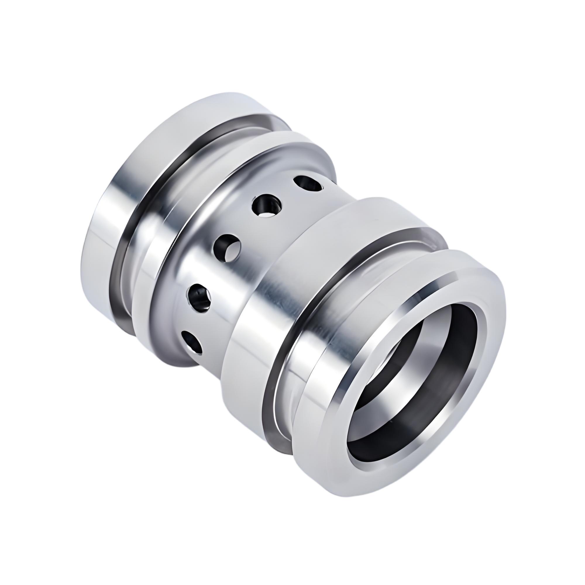
Compare the full electrode preparation route: rough machining, detail cutting, finishing, cleaning, inspection and mounting. A short cutting cycle can be offset by additional handling or verification. Ask the supplier to explain the proposed route for the actual geometry rather than quoting a general material machinability ranking.
Makino’s ram EDM article discusses copper deburring and graphite preparation in its treatment of electrode systems. Those observations provide useful process questions, but its historical numerical limits should not be treated as universal limits for current equipment. Obtain a current proposal for the intended machine, material and cavity.
Include the cost of rejected or damaged electrodes and the number of qualified tools required for the production plan. A complex detail that is easy to machine but difficult to protect may change the economics. Compare the time to a usable inspected electrode, not merely blank to machine exit. Keep electrode manufacture and cavity machining estimates separate so the basis for the purchasing decision remains visible.
For thin features, include inspection after handling and mounting in the preparation route so the comparison ends with a usable installed tool.
Wear and surface requirements
Evaluate wear and surface requirements under the selected electrical and material conditions. A material that performs well during roughing may not be the preferred choice for a particular finishing stage. The correct comparison is the finished cavity and total qualified process, rather than an unsupported claim that one electrode always wears less.
The 2020 electrode wear study abstract reports copper and graphite comparisons under specified workpieces and electrical factors. Its result is bounded by that experiment. Use it to justify testing local shape as well as material loss, not as a universal ranking for every electrode grade and machine setting.
Define which cavity surfaces require a named texture parameter, which corners control fit and whether downstream polishing is permitted. A process may reach a visual finish while altering a functional edge. Conversely, an acceptable dimensional profile does not establish the required surface condition. Keep those criteria separate when deciding whether a candidate electrode has passed its role in the manufacturing sequence.
If polishing is allowed, compare its dimensional effect on both candidates rather than assuming it only changes the appearance of the cavity.
Choose from the cavity and inspection plan
Start from the product requirements and work backward to the electrode roles. List the critical cavity dimensions, local details, texture requirements, access limits and permitted postprocessing. Then ask which candidate grade and sequence can demonstrate each item with credible evidence.
Do not require one material for every stage if a documented mixed strategy better serves the cavity. Conversely, a mixed strategy adds locating and process interfaces that also need control. Identify how each electrode is referenced and which tool creates the final accepted surface.
Relate the proposal to the EDM manufacturing review. If a cavity’s smallest feature cannot be inspected after machining, resolve the verification approach before material selection is finalized. An apparently favorable electrode cannot be judged from a result that the inspection plan cannot observe. Keep the selection conditional on the actual grade, workpiece state and process stage rather than freezing a broad copper or graphite preference into the drawing.
Weight the selection toward the most consequential feature failure, not the number of comparison categories in which one material appears preferable.
Compare complete copper and graphite preparation routes
The process map should connect the approved electrode model to manufacture, preinspection, mounting, roughing, finishing and cavity acceptance. Identify the points where the two material options require different preparation or handling. This makes the comparison reviewable without asking the buyer to specify every machine setting.
For a hypothetical deep recess with one fine internal rib, compare a complete copper proposal with a complete graphite proposal. Each must demonstrate the rib and the same cavity finish after its intended sequence. A trial that roughs one option and fully finishes the other does not provide a fair basis for cost or quality selection.
Include upstream references produced by turning or related machining. The electrode material does not correct an inconsistent workpiece locating surface. Also identify cleaning and any final polishing. The accepted process should show which operation owns the final geometry and how that geometry remains protected after EDM, rather than assuming all later work is dimensionally neutral.
Where different tools finish adjoining surfaces, verify their transition explicitly; acceptable individual surfaces can still leave an unwanted step at the boundary.
Match electrode candidates to one cavity acceptance matrix
Use a comparison matrix that records requirements and evidence, not a list of broad material advantages. Copper and graphite candidates should face the same cavity acceptance conditions even when their internal manufacturing routes differ. Note where an option needs additional tools or verification.
| Decision item | Copper proposal | Graphite proposal | Evidence |
|---|---|---|---|
| Fine detail | Document edge preparation | Document grade and detail integrity | Inspected electrode profile |
| Tool preparation | Include finishing and deburring | Include machining and handling | Qualified preparation route |
| Local wear | Assess assigned stage | Assess assigned stage | Tool and cavity measurements |
| Surface texture | Verify specified finish | Verify specified finish | Defined parameter and method |
Mitutoyo’s surface texture guide distinguishes parameters and profile evaluation. Use one agreed definition for the comparison. A photograph labeled mirror finish and a numerical roughness report are different evidence types; neither should silently replace the specified surface requirement.
Qualify material choice using representative cavity trials
A selection trial should use representative cavity geometry, workpiece material and final acceptance. Record the exact electrode grades, tool condition, assigned stages and relevant process identifiers. Include the cost and time necessary to produce passing inspected tools and cavities, rather than comparing only a convenient portion of the route.
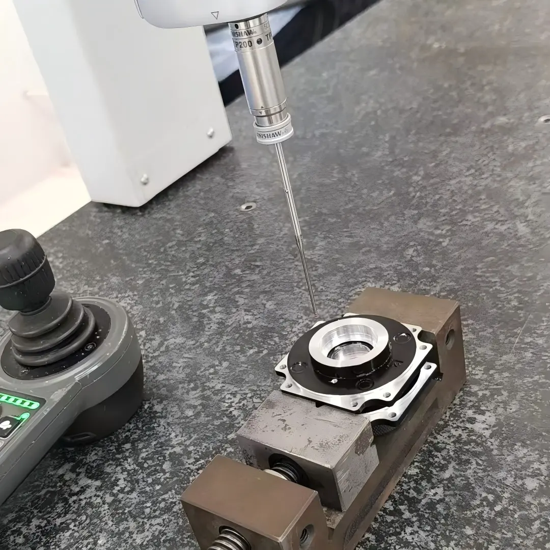
Repeatable measurement supports a fair comparison. Renishaw’s metrology fixturing overview describes consistent holding for dimensional inspection. Apply compatible reference and support conditions to both candidate results so setup differences are not mistaken for a material advantage.
Retain the failed as well as passing evidence. If one candidate needs a revised finish tool or a different allowance, include that revision in the final proposal. Define the resulting approval through the agreed inspection requirements. One successful cavity establishes the tested combination, not every graphite grade or every copper tool. Production controls should preserve the inputs that made the comparison meaningful.
Document which costs change if the required cavity count increases, including additional inspected tools and the verification needed after a replacement electrode is installed.
Define the electrode substitution scope before quoting
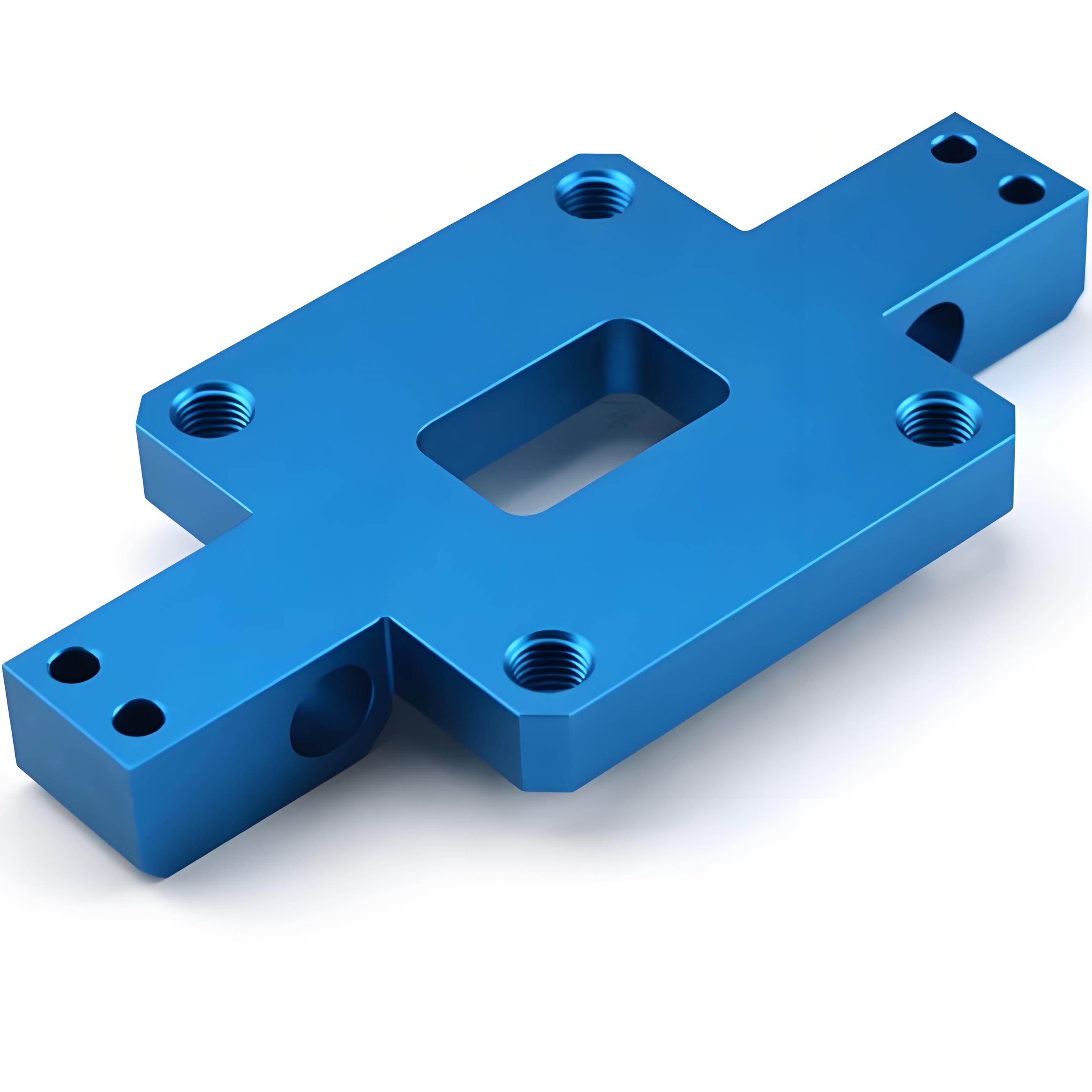
The RFQ should state the conductive workpiece grade and condition, cavity model, deepest regions, smallest details and surface requirements. Identify whether the buyer is requesting a material recommendation or requiring an existing qualified electrode route. If an alternative is proposed, define what equivalence must demonstrate.
Ask for the complete electrode plan, including inspected tool quantity, roughing and finishing roles, expected replacement basis and permitted postprocessing. Keep the cost assumptions explicit. A low material price is not comparable with a complete tooling quote unless both cover the same accepted result.
Resolve access for dimensional and texture measurement, particularly on deep sidewalls and thin ribs. State any restriction on polishing, local rework or repair. When a material substitution changes the tool preparation, electrical stage or finishing allocation, review the relevant trial evidence. The released requirement should protect the finished cavity while leaving the specialist appropriate freedom to choose a documented and verifiable electrode system.
FAQ
Is graphite always faster than copper for EDM?
No universal speed ranking establishes the time to a finished acceptable cavity. Compare electrode preparation, roughing, finishing, inspection and any required additional tools for the actual geometry. Machine technology, electrode grade and workpiece condition affect the proposal. A faster roughing stage can still produce a longer total route if the smallest details require more finishing or rework. Request estimates on the same accepted result rather than one isolated operation.
Can copper and graphite share the same electrode model?
They may share a common product geometry reference, but the manufactured tool model also reflects the intended gap allowance, motion and assigned process stage. Do not assume one tool file can be exchanged without review. Confirm the required electrode geometry, locating system and preparation method for each option, then inspect the resulting tools. A material substitution is only meaningful if the approved process still produces the specified cavity and local details.
Should the product drawing require a specific electrode material?
Specify it when a qualified product or process requirement makes that restriction necessary. Otherwise, the finished cavity requirements and verification plan may provide a better basis for a supplier recommendation. If an existing process uses a controlled material, evaluate proposed substitutions through the applicable change process. A general preference for copper or graphite should not replace evidence about the exact grade, cavity, surface condition and manufacturing sequence.
Conclusion
Choose the electrode system that produces the required cavity with a documented, inspectable route. Compare tool detail integrity, preparation, local wear and finishing against the same acceptance conditions. The name copper or graphite is too broad to establish either the result or its cost.
Keep the selected grade and stage allocation connected to the trial evidence. A later substitution can change more than the material on a purchase line; it can alter tool geometry, handling and the finishing sequence. For a review with 6CProto, send the cavity model, critical detail sections and finish requirements for quotation. Request the complete tooling and verification proposal so the comparison ends with an accepted feature rather than a preferred material label.
{“@context”: “https://schema.org”, “@type”: “FAQPage”, “mainEntity”: [{“@type”: “Question”, “name”: “Is graphite always faster than copper for EDM?”, “acceptedAnswer”: {“@type”: “Answer”, “text”: “No universal speed ranking establishes the time to a finished acceptable cavity. Compare electrode preparation, roughing, finishing, inspection and any required additional tools for the actual geometry. Machine technology, electrode grade and workpiece condition affect the proposal. A faster roughing stage can still produce a longer total route if the smallest details require more finishing or rework. Request estimates on the same accepted result rather than one isolated operation.”}}, {“@type”: “Question”, “name”: “Can copper and graphite share the same electrode model?”, “acceptedAnswer”: {“@type”: “Answer”, “text”: “They may share a common product geometry reference, but the manufactured tool model also reflects the intended gap allowance, motion and assigned process stage. Do not assume one tool file can be exchanged without review. Confirm the required electrode geometry, locating system and preparation method for each option, then inspect the resulting tools. A material substitution is only meaningful if the approved process still produces the specified cavity and local details.”}}, {“@type”: “Question”, “name”: “Should the product drawing require a specific electrode material?”, “acceptedAnswer”: {“@type”: “Answer”, “text”: “Specify it when a qualified product or process requirement makes that restriction necessary. Otherwise, the finished cavity requirements and verification plan may provide a better basis for a supplier recommendation. If an existing process uses a controlled material, evaluate proposed substitutions through the applicable change process. A general preference for copper or graphite should not replace evidence about the exact grade, cavity, surface condition and manufacturing sequence.”}}]}