

Explore CNC Programming & Process Engineering Guides
A blind cavity can become unstable late in a burn even though its opening looks easy to flush. The fluid entering the mouth may circulate past the entrance without carrying debris out of the deepest gap. EDM blind cavity flushing should therefore be reviewed as a complete transport route rather than a nozzle pressure setting.
The objective is to maintain useful discharge conditions while preserving the electrode and the feature. More forceful fluid delivery is not automatically a better solution, particularly around narrow ribs or slender electrodes. The process needs a way for fresh dielectric to reach the working region and contaminated fluid to leave without creating unacceptable mechanical or geometric effects.
For a buyer, the useful questions concern access, motion and evidence: where can fluid enter and leave, what changes as the cavity deepens and which inspection establishes the finished result? This article focuses on those questions. Local electrode wear still matters, but it should not obscure a debris removal problem that appears only in the final depth or around a restricted pocket.
Debris concentration in blind features
The deepest gap can contain a different debris concentration from the visible fluid outside the cavity. A fluid jet at the opening does not prove renewal at the working face. Review the cavity walls, electrode shape and possible exit routes together, especially where broad faces or narrow side gaps restrict circulation.
Makino’s ram EDM process explanation describes the dielectric and removal of eroded material from the gap. Its discussion of localized debris provides a mechanism for questioning an apparently adequate external flow. Do not convert that mechanism into an unsupported universal cavity depth limit.
Map the likely stagnant regions in a section and identify what changes as the tool advances. A recess that is easy to flush near the surface may become more restricted near its floor. Keep observations of unstable operation, local surface defects and depth together in the trial record. If all are reduced to a single total burn time, the process can conceal the location where its useful transport route stopped working.
Where several blind regions share an opening, identify their separate exchange paths. One visible outlet does not establish that every pocket is renewed.
External internal and orbital flushing
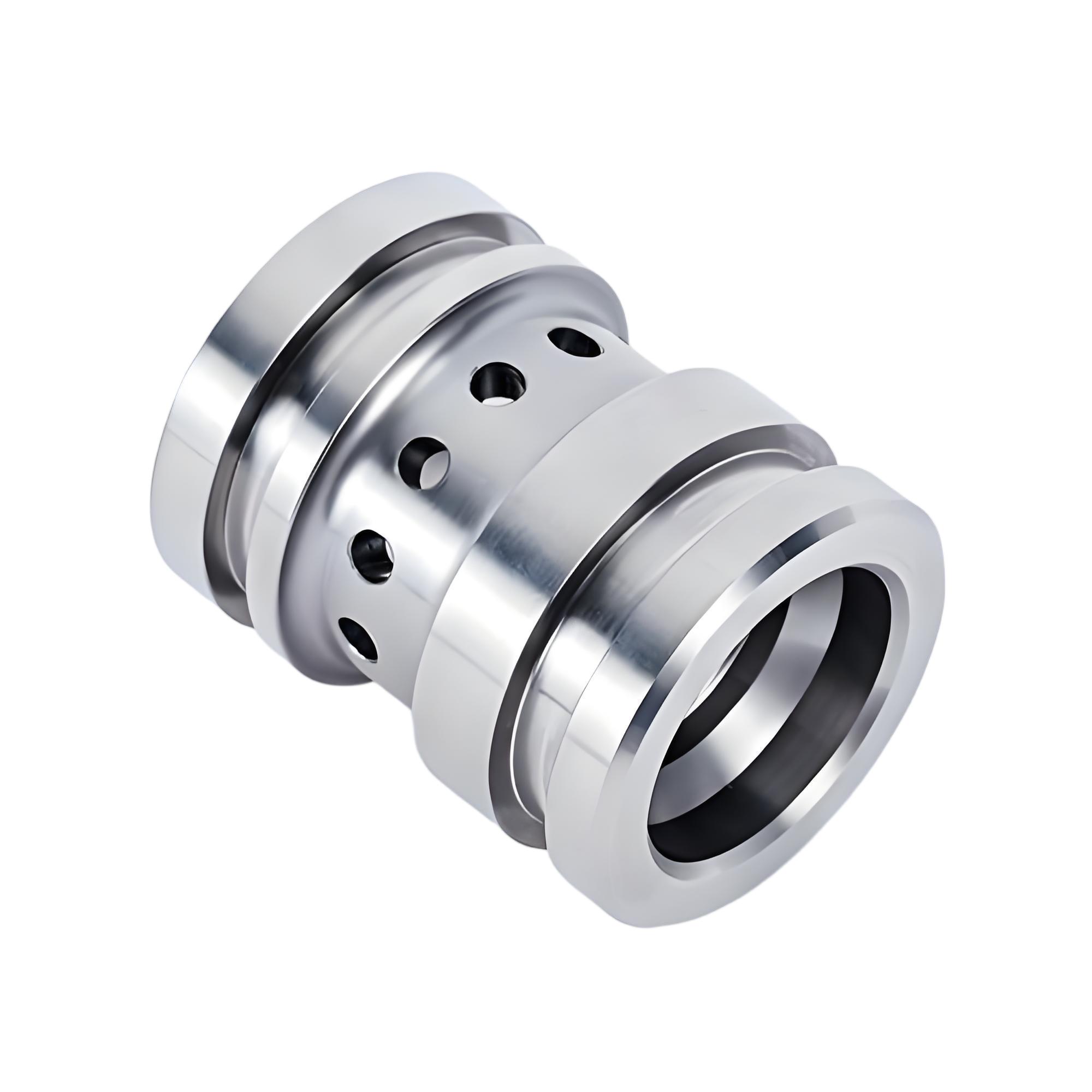
External flow, an internal electrode passage and motion that renews the gap create different fluid routes. Select them from the cavity and permitted tool construction. An internal passage can improve access to a restricted region but may change electrode detail or leave a feature that must be accommodated in the process.
An orbital or jump motion can create temporary space for exchange. Its effectiveness still depends on the available route and chosen motion; the name of the function does not establish that debris leaves every blind region. Ask the specialist to show how the proposed sequence reaches the controlling location.
Separate ordinary dielectric management from a specialized additive system. Makino’s discussion of finishing technology explains that additive processes require compatible fluid control and filtration. A supplier should not add an unfamiliar fluid or change filtration to solve flushing without evaluating the qualified system. Keep any revised fluid, electrode passage or motion sequence linked to the same cavity acceptance requirements before approving the change.
Thin ribs and electrode stability
A narrow electrode detail needs both manufacturing integrity and stable support during EDM. Evaluate fluid direction and tool projection alongside the gap renewal strategy. A nozzle arrangement that reaches a deep region may also load a slender feature in an unfavorable direction.
Makino’s electrode material discussion identifies mechanical properties and resistance to flushing related deflection as material selection considerations. Use the actual electrode grade and geometry for the assessment. A broad statement that EDM has no cutting force should not be expanded into a claim that every electrode experiences no mechanical load.
Check the incoming tool and its mounting before interpreting a local cavity error as an electrical problem. A bent, chipped or poorly seated detail can change the effective gap and fluid route. Where support or a passage is added, evaluate its influence on the final cavity. The process should preserve the critical rib or corner, not merely continue the burn. Record any permitted tool redesign on the approved electrode model rather than improvising it during a difficult trial.
Retain the tool inspection before changing the flushing arrangement, so a preexisting damaged rib is not attributed to the new fluid direction.
Validate the cavity after finishing
Inspect the cavity after the final discharge and any subsequent finishing, using the product’s functional references. Check the depth, local profile and accessible texture regions separately. A stable looking process display or a shorter cycle does not prove that the floor and sidewalls meet acceptance.
Inspect the locations that were most difficult to flush, not only the opening. If the bottom is inaccessible to the proposed instrument, resolve a qualified alternative before release. A replica, sectioned trial or other method must have an agreed capability and limitation; its name alone does not establish the result.
Mitutoyo’s surface texture guide distinguishes surface parameters and profile evaluation. Specify which parameter is required and how it can be measured inside the cavity. A bright local surface and a numerical roughness result are different observations. For the EDM feature review, identify any area where geometry can be measured but surface condition remains unverified, then close that particular evidence gap.
Map dielectric entry, debris exit and electrode motion
Show the electrode approach, fluid entry, intended exit and available motion in one section. Add the tool holder, cavity depth changes and any blind side pockets. The drawing should make it possible to see whether a proposed jump or orbit has room to occur without collision or unintended material removal.
Consider a hypothetical deep rectangular recess with a narrow rib at one end. External flow reaches the broad opening, while the rib region remains sheltered. A useful trial compares a defined alternative transport route or motion at that region, then inspects the rib and adjacent floor. Simply increasing a nozzle setting changes a control input without demonstrating that the sheltered gap receives renewal.
Identify upstream references created by other machining operations. A stable EDM and inspection setup requires those surfaces to remain usable. Record the point at which the cavity becomes difficult to inspect, so evidence can be collected before later operations hide access or alter the surface that the trial is intended to evaluate.
Connect flushing symptoms to local cavity measurements
Use the verification matrix to connect a process symptom with a finished characteristic. Debris control, electrode stability and surface integrity can influence one another, but the evidence for one does not establish all the others. Preserve the location and stage of each observation.
| Question | Evidence | Boundary |
|---|---|---|
| Did the route reach the restricted region? | Defined flow and motion trial with local results | External circulation alone is insufficient |
| Did the electrode remain stable? | Tool condition and cavity profile | Overall depth cannot prove local form |
| Did finishing meet texture requirements? | Specified parameter at agreed locations | Appearance cannot establish every surface metric |
| Did the cavity meet geometry? | Depth and local profile from datums | Opening size cannot prove the floor |
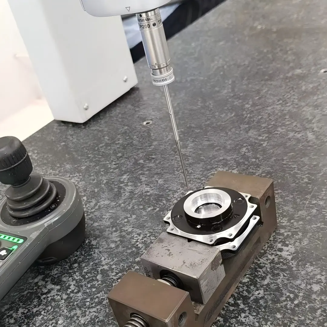
Use reproducible workholding for comparisons. Renishaw’s metrology fixturing information describes repeatable setups; here, the fixture must also preserve access to the difficult internal feature.
For inaccessible surfaces, state the qualified alternative and its sampling boundary before production, rather than discovering the measurement limitation after the cavity is complete.
Qualify gap renewal at full cavity depth
Qualify a representative material, cavity depth, electrode and fluid management sequence. A shallow coupon may help investigate a local mechanism, but it does not establish the deepest production gap. Identify which geometric restrictions the trial reproduces and which remain outside its scope.
Change the relevant factor deliberately and retain the baseline. If an electrode passage, orbital motion and fluid system are changed together, the result can qualify the combined route but may not identify the cause of the original instability. State that distinction in the trial plan and inspect the local zones after finishing.
The public scope of ASME Y14.5 supports clear geometric communication, while the actual test and acceptance remain application specific. Link the trial to the drawing and inspection requirements. Approve the tested configuration and define which changes require review, especially a deeper cavity, a different electrode detail or a finishing process that alters how the gap is renewed.
Flushing access and local finish evidence for an RFQ
Provide cavity sections, conductive material and condition, deepest regions, minimum gaps and fragile electrode details. Identify surfaces whose local profile or texture controls function. Include restrictions on internal electrode passages, witness features and any permitted finishing after EDM.
Ask for a proposed transport route and motion strategy, along with the inspection evidence for the restricted locations. The buyer does not need to prescribe nozzle hardware, but should be able to see how the specialist plans to remove debris from the controlling region. A statement that high pressure flushing is available does not answer that question.
Resolve whether a representative trial, destructive sample or special inspection is included in the quotation. Record what would make the process unacceptable, such as local geometry outside the drawing or unverified surface condition at the floor. Keep the acceptance attached to the feature rather than a preferred flushing label. This allows appropriate technical alternatives while preventing an operating change from silently relaxing the product requirements.
Include the permitted electrode modifications explicitly. A passage added during troubleshooting may change the tool and therefore require a revised inspection or finishing sequence.
FAQ
Does higher flushing pressure always improve a blind cavity?
It changes an input, but does not prove that fluid reaches and leaves the restricted working region. It can also affect a slender electrode mechanically. Review the complete flow route and tool stability before increasing delivery. A representative trial should inspect the deepest or most sheltered feature after finishing. The desired result is controlled geometry and surface condition, not the highest available nozzle pressure or the most visible circulation.
Can an internal electrode passage solve every flushing problem?
It may provide access to a restricted region, but it changes the electrode construction and can affect local detail or the machining sequence. The route still needs an exit for contaminated fluid. Review the passage with the cavity geometry, permitted witness conditions and finishing plan. Qualify the actual tool rather than assuming that the presence of a hole establishes gap renewal throughout a deep or complex cavity.
Is a shorter burn enough evidence to approve a flushing change?
It can support a productivity comparison under controlled conditions, but it does not establish finished acceptance. Inspect the relevant depth, corners, ribs and surface regions after the revised sequence. Record whether electrode condition, electrical stages or fluid also changed. A shorter run with an unacceptable local feature has not solved the manufacturing requirement, and a successful shallow trial does not automatically establish the full production depth.
Conclusion
Approve a blind cavity flushing route when the restricted gap can be renewed without sacrificing electrode stability or the finished feature. Flow entry, exit and motion must remain connected to the deepest geometry. Pressure and cycle time are useful process information, but the cavity still needs local dimensional and surface evidence.
When a trial is unstable, preserve its stage and location before changing multiple inputs. That record helps distinguish a transport restriction from tool damage or a different process issue. For a review with 6CProto, send cavity sections, access limits and local acceptance requirements for quotation. Include any restriction on electrode passages or postprocessing so the proposed route can be evaluated against the part that will actually be delivered.
{“@context”: “https://schema.org”, “@type”: “FAQPage”, “mainEntity”: [{“@type”: “Question”, “name”: “Does higher flushing pressure always improve a blind cavity?”, “acceptedAnswer”: {“@type”: “Answer”, “text”: “It changes an input, but does not prove that fluid reaches and leaves the restricted working region. It can also affect a slender electrode mechanically. Review the complete flow route and tool stability before increasing delivery. A representative trial should inspect the deepest or most sheltered feature after finishing. The desired result is controlled geometry and surface condition, not the highest available nozzle pressure or the most visible circulation.”}}, {“@type”: “Question”, “name”: “Can an internal electrode passage solve every flushing problem?”, “acceptedAnswer”: {“@type”: “Answer”, “text”: “It may provide access to a restricted region, but it changes the electrode construction and can affect local detail or the machining sequence. The route still needs an exit for contaminated fluid. Review the passage with the cavity geometry, permitted witness conditions and finishing plan. Qualify the actual tool rather than assuming that the presence of a hole establishes gap renewal throughout a deep or complex cavity.”}}, {“@type”: “Question”, “name”: “Is a shorter burn enough evidence to approve a flushing change?”, “acceptedAnswer”: {“@type”: “Answer”, “text”: “It can support a productivity comparison under controlled conditions, but it does not establish finished acceptance. Inspect the relevant depth, corners, ribs and surface regions after the revised sequence. Record whether electrode condition, electrical stages or fluid also changed. A shorter run with an unacceptable local feature has not solved the manufacturing requirement, and a successful shallow trial does not automatically establish the full production depth.”}}]}