

Explore CNC Programming & Process Engineering Guides
Changing a milling feed without checking the spindle speed changes the load assigned to every cutting edge. Changing the toolpath can change the chip thickness again, even when the programmed feed remains identical. A useful process review therefore follows the calculation into the cut rather than treating a calculator result as a complete cutting recommendation.
For chip load vs feed rate, the essential relationship is table feed equals feed per tooth multiplied by spindle revolutions per minute and the effective number of teeth per revolution. That relationship connects quantities; it does not select a suitable tool, establish a stable setup, or account automatically for radial engagement.
A buyer comparing cycle-time proposals should ask which inputs describe the approved operation. A high feed number can reflect more teeth, higher speed, or a different engagement strategy. Those changes have different consequences for tool access, chip evacuation and finished geometry.
The following checks apply to milling with a defined rotating cutter. Turning uses a different cutting arrangement and should remain with the turning process. For a milling quotation, request the cutter identity, operation and assumptions alongside any proposed productivity figure.
How does chip load vs feed rate connect milling inputs?
Feed rate combines chip load, speed and teeth.
For a defined milling cutter, multiply feed per tooth by revolutions per minute and effective teeth per revolution; keep the toolmaker’s engagement assumptions separate from this dimensional relationship.
Write the relationship as vf = fz × n × zc. Here vf is table feed in mm/min, fz is feed per tooth in mm/tooth, n is spindle speed in revolutions/minute, and zc is the effective tooth count per revolution. The units cancel to give linear travel per minute. Conversely, fz = vf/(n × zc).
Feed per revolution, fn, is vf/n, so fn = fz × zc for the same defined operation. Confusing fn with fz multiplies or divides the intended edge loading by the tooth count. Sandvik Coromant's milling definitions distinguish these quantities explicitly.
Label the original value before entering it into CAM. A toolmaker’s feed-per-tooth recommendation should remain associated with its specified tool geometry, material group and engagement conditions; a copied number without that context cannot establish a production setting.
Number of effective cutting edges
Count the edges that perform equivalent work in one revolution. A conventional four-flute end mill normally uses four in the feed relationship, although all four flutes need not be engaged simultaneously. Instantaneous engagement and effective teeth per revolution answer different questions.
Indexable cutters need more care. An insert count can differ from the number of effective teeth at a particular axial location. Staggered rows, special finishing inserts and multi-edge arrangements can invalidate a simple count of visible inserts. Consult the cutter’s technical data rather than guessing from a photograph.
Runout also means the average arithmetic feed per tooth is not necessarily distributed equally. One edge can cut a larger share while another rubs. Inspect cutter seating, holder condition and actual runout when wear appears concentrated on particular edges.
The shoulder-milling application guidance connects cutter selection with stability, chip evacuation and tool holding. Specify the actual cutter assembly for the CNC milling operation; substituting a different tooth arrangement requires a fresh calculation and process review, even when diameter stays unchanged.

Radial engagement and chip thinning
Feed per tooth is a kinematic input, while chip thickness varies along the engagement arc. At small radial engagement, the maximum chip thickness can be below the programmed feed per tooth. Entering angle changes the relationship further. These effects explain why two operations with equal fz can create different cutting conditions.
Use the toolmaker’s model for the actual cutter and engagement. Applying a radial chip-thinning multiplier outside its geometry assumptions can demand excessive feed when the tool enters a corner, changes stock allowance or reaches a wider engagement. A CAM strategy that controls engagement reduces this variation but still needs verification against the remaining stock.
Entering-angle and chip-thickness guidance provides the geometric context; it should accompany the specific tool’s cutting data. Avoid transferring a multiplier between round-insert, high-feed and square-shoulder cutters.
The review should identify where engagement is highest, not merely quote its nominal value on a long straight pass. Rest machining and uneven stock from an earlier operation can change the local cut without changing the programmed feed word.
Check units and source assumptions
Keep cutting speed, spindle speed and feed in separate fields. Cutting speed describes motion at the cutting diameter; spindle speed describes revolutions per minute. A value in metres per minute cannot be placed directly into the rpm term of the feed equation.
Likewise, distinguish millimetres per minute, inches per minute, millimetres per revolution and millimetres per tooth. Unit conversion must precede comparison. Keep the original units visible in the process record so that an apparently unusual value can be traced back to its source.
The source recommendation also needs an operation label: roughing or finishing, slotting or peripheral milling, material condition, axial depth, radial width and cutter overhang. A manufacturer’s value for a stable, short tool is not automatically suitable for a deep cavity with a long extension.
Record whether CAM already applies chip-thinning compensation. Applying a second manual multiplier can overfeed the same operation. When comparing proposals, use the same geometry and stock condition; a faster calculation with a different allowance is not evidence of a more efficient equivalent process.
Feed modes and units in the posted milling program
A correct calculation can still produce the wrong motion if the controller interprets the feed word under another mode. Confirm the machine’s active unit system and feed mode in the actual posted program, including the startup blocks and transitions between operations.
The Hurco feed-functions documentation defines G94 as feed per minute, while the referenced Haas mill documentation defines G95 as feed per revolution. These definitions belong to their documented control families. Check the machine-specific manual and postprocessor before transferring the codes to another control.
| Quantity | Example unit | Required agreement |
|---|---|---|
| Feed per tooth | mm/tooth | Tool data and effective teeth |
| Spindle speed | rev/min | Posted spindle command |
| Table feed | mm/min | Feed mode and linear units |
| Feed per revolution | mm/rev | Controller interpretation |
Multi-axis inverse-time feed requires separate postprocessor handling and is outside this simple table-feed calculation. For 5-axis machining, review rotary motion, tool-center-point behavior and the specific control documentation as part of the program approval.

A checked conversion from tooth feed to table feed
Consider an arithmetic example with an assumed four-effective-tooth cutter, spindle speed n = 6,000 rev/min and feed per tooth fz = 0.04 mm/tooth. These inputs illustrate conversion only; they are not cutting recommendations for a material or machine.
The calculated table feed is vf = 0.04 × 6,000 × 4 = 960 mm/min. Feed per revolution is fn = 960/6,000 = 0.16 mm/rev. The reverse calculation gives 960/(6,000 × 4) = 0.04 mm/tooth, confirming the intended relationship.
If spindle speed is reduced to 4,000 rev/min while table feed remains 960 mm/min, the calculated feed per tooth becomes 960/(4,000 × 4) = 0.06 mm/tooth. That is a 50% increase in the arithmetic edge-loading input. Keeping fz at 0.04 instead requires vf = 640 mm/min.
This calculation excludes runout, chip thinning, acceleration, corner engagement and tool deflection. It establishes what the numbers mean, after which the toolmaker’s limits and the actual machining setup determine whether any proposed combination is acceptable.
Verifying commanded motion through corners and entries
Simulation should examine the stock remaining at each engagement, the cutter assembly and holder clearance, and the path through corners. A collision-free centerline does not confirm that the intended chip thickness or stable cutting conditions will occur throughout the pass.
During a controlled first-part run, compare commanded and actual spindle speed and feed. Feed overrides and acceleration limits can make the achieved motion differ from the programmed value, particularly on short segments. Record the machine state when assessing finish or tool wear.
Inspect chips, cutting edges and finished surfaces together. Sandvik's milling troubleshooting guidance treats vibration, chip recutting and fixture weakness as separate contributors; lowering feed alone may leave the underlying problem unresolved. Do not interpret spindle-load indication as a direct measurement of individual tooth load.
Document entry and exit behavior as well as the steady pass. The direction of milling changes chip formation and force direction, so reversing a toolpath can change the result without changing vf, n or zc. Accept the operation against dimensional and surface requirements, not a calculated feed number alone.
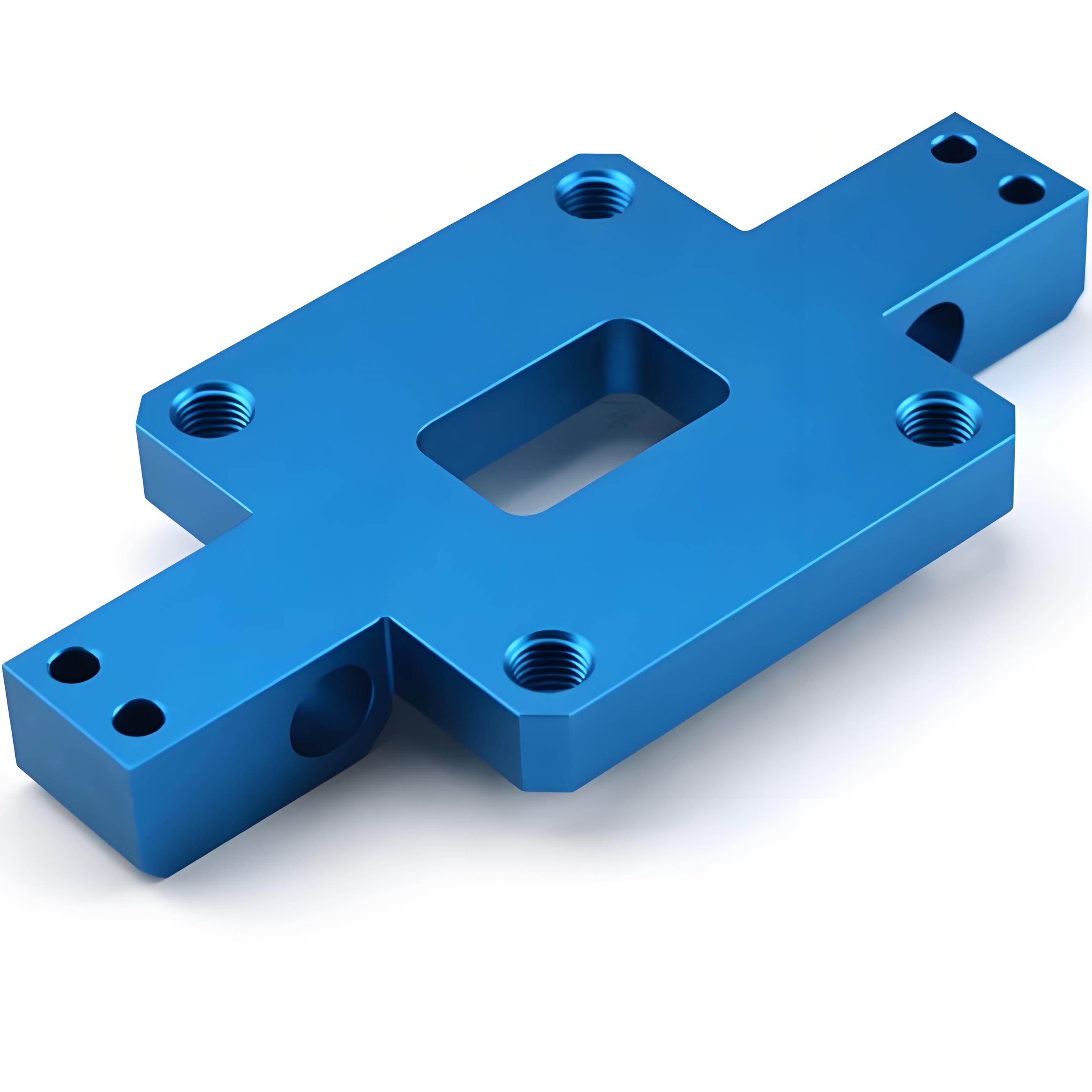
Retaining the approved milling inputs and trial state
The released process record should let another programmer reproduce the reasoning. Include tool and holder identification, effective tooth count, cutting diameter, material condition, stock allowance, axial and radial engagement, spindle speed, feed mode and programmed feed. Attach the source cutting-data revision where it influenced the selection.
Separate calculated inputs from approved production observations. The former establish arithmetic traceability; the latter show how a specific machine, fixture and workpiece behaved. A successful first part does not remove the need to monitor wear or verify another setup with different overhang.
Record any local feed reductions, compensation settings and override used during approval. Otherwise, a repeat run at the nominal program value may differ from the run that produced the accepted part. Identify who may change the operation and which changes require another dimensional check.
For purchasing, request a cycle-time breakdown that distinguishes cutting, positioning, tool changes and handling. Feed-rate improvements affect only the relevant portion. This prevents a theoretical increase in linear feed from being mistaken for an equal reduction in the delivered part’s total manufacturing time.
FAQ
Can I compare two quotations using feed rate alone?
Only when the operations are genuinely comparable. Ask whether both proposals use the same material condition, stock allowance, tool access, finish requirements and inspection scope. A higher feed may result from more effective teeth or a different engagement strategy rather than a higher load per edge. It may also affect only a small portion of the cycle. Compare total machining and handling time, tool consumption and accepted-part output before treating the feed number as a commercial advantage.
Does a feed override preserve the calculated chip load?
Not necessarily. A feed override changes the commanded linear motion, while a spindle override may change rotational speed independently. Their combined effect determines the arithmetic feed per tooth. Some controls and modes link particular functions, so check the machine documentation and actual displayed values. Record both overrides during process approval. A part accepted with an undocumented override does not establish that the nominal posted program will reproduce the same cutting conditions on the next run.
Should the drawing specify the production chip load?
Usually the drawing should define the product's material, geometry, finish and acceptance requirements. Chip load belongs in the controlled manufacturing process unless a specific contractual process requirement makes it necessary. Putting a generic feed value on the product drawing can prevent legitimate tooling improvements without guaranteeing the required surface. Where process restrictions matter, define their purpose, approval route and required evidence so that a supplier can propose a technically justified change without weakening product acceptance.
Conclusion
A defensible feed calculation preserves the meaning of every input: feed per tooth, spindle speed, effective teeth and controller feed mode. Engagement then determines how those inputs become chips, forces and surface condition in the real operation. Retain both the calculation and the first-part evidence so that a tooling or program change can be assessed against the same acceptance requirements.
For a component review, send 6CProto the model and drawing for a quotation, with the material condition, functional surfaces and expected quantity. Include any existing machining restrictions so the proposed route can be assessed against the actual part requirements.
{“@context”: “https://schema.org”, “@type”: “FAQPage”, “mainEntity”: [{“@type”: “Question”, “name”: “Can I compare two quotations using feed rate alone?”, “acceptedAnswer”: {“@type”: “Answer”, “text”: “Only when the operations are genuinely comparable. Ask whether both proposals use the same material condition, stock allowance, tool access, finish requirements and inspection scope. A higher feed may result from more effective teeth or a different engagement strategy rather than a higher load per edge. It may also affect only a small portion of the cycle. Compare total machining and handling time, tool consumption and accepted-part output before treating the feed number as a commercial advantage.”}}, {“@type”: “Question”, “name”: “Does a feed override preserve the calculated chip load?”, “acceptedAnswer”: {“@type”: “Answer”, “text”: “Not necessarily. A feed override changes the commanded linear motion, while a spindle override may change rotational speed independently. Their combined effect determines the arithmetic feed per tooth. Some controls and modes link particular functions, so check the machine documentation and actual displayed values. Record both overrides during process approval. A part accepted with an undocumented override does not establish that the nominal posted program will reproduce the same cutting conditions on the next run.”}}, {“@type”: “Question”, “name”: “Should the drawing specify the production chip load?”, “acceptedAnswer”: {“@type”: “Answer”, “text”: “Usually the drawing should define the product’s material, geometry, finish and acceptance requirements. Chip load belongs in the controlled manufacturing process unless a specific contractual process requirement makes it necessary. Putting a generic feed value on the product drawing can prevent legitimate tooling improvements without guaranteeing the required surface. Where process restrictions matter, define their purpose, approval route and required evidence so that a supplier can propose a technically justified change without weakening product acceptance.”}}]}