

Explore CNC Programming & Process Engineering Guides
A welded frame can contain ample extra material yet still fail to clean up at one mounting pad. The stock may be on the wrong face, the datum transfer may place the machining envelope incorrectly, or clamping may flatten the frame during cutting and let it spring afterward. Adding the same allowance everywhere addresses none of those mechanisms reliably.
Welded assembly machining allowance should describe where material must remain relative to the finished geometry. The requirement is local and directional. It needs a stable locating plan and evidence of the welded condition that enters machining.
Separate the fabrication shape from the final product envelope. Show the faces that will be machined, the references used to establish them and the minimum material that must remain after cleanup. Extra stock is useful only when the finishing operation can reach it without violating another requirement.
The fabricated assembly service supplies the joining context. This guide concentrates on stock placement and its verification, rather than repeating general welding-distortion prevention or assigning an unsupported allowance to every weldment.
Choose the surfaces to finish machine
Put finishing stock on the functional interfaces.
Identify mounting pads, bearing seats, sealing faces and locating bores individually, then define their final relationships before deciding which welded surfaces need additional material for machining cleanup.
Machining every visible surface can increase cost and remove useful section without improving function. Conversely, leaving a critical interface as welded may make its relationship to another feature difficult to control. Start with the assembled product’s load and location requirements.
Distinguish a face that must clean up completely from one that merely needs a specified region to contact. Show any permitted unmachined area explicitly. An instruction to machine as necessary leaves acceptance uncertain when a low area remains outside the actual contact footprint.
The ASME dimensioning-and-tolerancing framework supports communicating geometric relationships and functional references. It does not prescribe stock allowance. Define the final requirement first, then review whether the proposed fabrication and machining route can leave enough material in the correct places. A face-specific allowance can be more economical and more inspectable than a generous blanket note.
Datum transfer from weldment to fixture
Establish how the as-welded assembly enters the machining coordinate system. Rough plate edges, temporary tabs and welded pads may offer convenient contact, but they need a documented relationship to the final datums. Otherwise the available stock can be shifted away from the feature that needs it.
Review the first operation separately from later operations. Once an initial face or bore is finished, it may provide a better reference for the remaining work. The sequence should preserve access and enough support while transferring location deliberately.
TWI’s discussion of restraint and distortion explains that movement can occur when a welded component is released from restraining equipment. That is a reason to inspect the condition entering machining rather than assuming the welding fixture defines permanent geometry.
Use setup sketches that identify contact points, clamps and the intended restraint. Distinguish locating from forcing the assembly into shape. For CNC machining, supply the final datum scheme and allow the proposed setup to be reviewed against it. A repeatable fixture position is valuable only if it produces the required part after release.
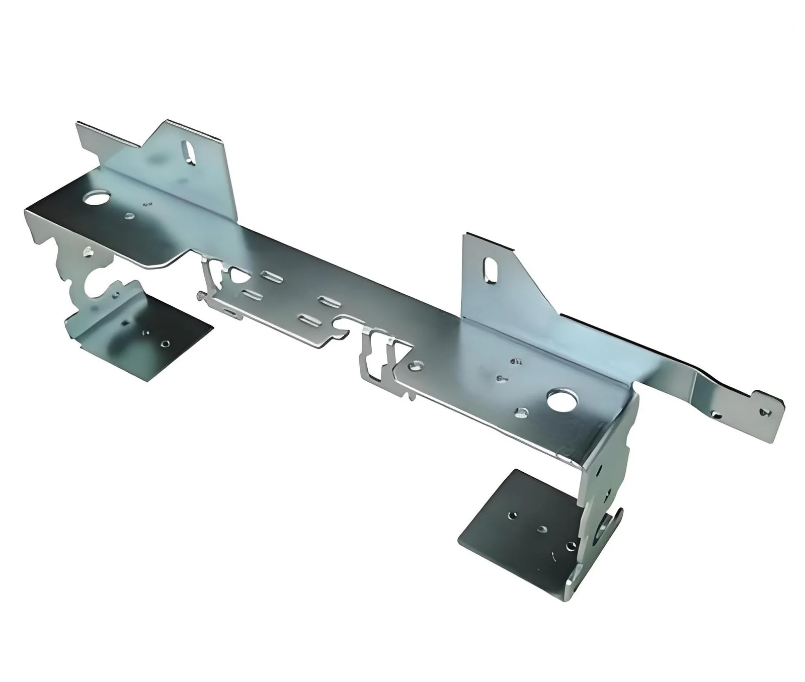
Stock allowance and local stiffness
Allowance needs to cover the finishing envelope without making the local feature unworkable. A thin pad with a large unsupported span may move under clamping or cutting. Increasing its height before machining does not automatically solve the stiffness of the remaining section.
Consider the lowest as-welded material position relative to the selected machining setup. Include relevant variation in fabrication, locating and finishing, while avoiding double counting the same movement in several allowance terms. The allowance proposal should state its reference and direction.
For a hypothetical pad, 0.8 mm of stock is 0.5 mm greater than an assumed 0.3 mm minimum cleanup requirement. Machining to the final plane removes 0.8 mm at that point. This geometry assumes unchanged setup and shape; it does not establish final wall thickness.
TWI’s joining-process simulation overview stresses that distortion predictions depend on material data and modeling assumptions. Use predictions to inform a local stock proposal, then compare them with representative fabrication evidence. Do not present a simulation result as a guaranteed cleanup margin for an untested weld sequence.
Inspect after machining and release
Inspect the final relationship in the condition specified by the drawing. A machined plane can be correct while the assembly is clamped and different after unloading. Distinguish fixture-state process checks from the dimensional evidence used for product acceptance.
Measure the relevant interfaces after the operation sequence is complete. If subsequent heat treatment, stress relief or another machining stage is part of the approved route, the earlier report is intermediate evidence. Record when each measurement was taken.
TWI’s back-to-back assembly guidance describes separation as a stage at which welded components may change shape. Its particular technique is not a general recommendation for every frame, but it illustrates why the release stage belongs in the process review.
Compare cleaned surfaces with minimum remaining section and local features such as threads or weld toes. A face that cleans up can still be too low, too thin or incorrectly related to a bore. If the result changes after release, investigate restraint and sequence rather than simply taking another cut. Further removal cannot restore material already lost from a critical pad.
Pad, bore and sealing-face stock requirements
Use the drawing package to connect each finishing feature with its fabrication input and final acceptance. A global stock note is difficult to apply when pads, flanges and bores face different directions. Show where a requirement is local and where several features share one setup relationship.
The matrix below organizes the information without assigning numerical allowances. Establish those from the approved design and demonstrated fabrication route.
| Feature | Fabrication concern | Final verification |
|---|---|---|
| Mounting pads | Lowest point relative to machining datum | Plane and pad relationship after release |
| Bearing bore | Stock around complete bore envelope | Size, location and axis relationship |
| Sealing face | Cleanup across required contact region | Geometry and specified texture |
| Thin flange | Support and minimum remaining section | Thickness and released shape |
Record the inspection reference on the same feature view. This prevents the fabricator, machinist and inspector from using different definitions of available stock. An allowance measured from a rough edge should not quietly become a final dimension from a machined datum.
A four-pad trial through machining and unclamping
A local weld coupon can help evaluate a joining detail, but it rarely reproduces the stiffness and datum transfer of a complete frame. Use a representative fabrication or a deliberately justified mock-up when the question is whether several pads clean up in one finishing setup.
For a hypothetical four-pad frame, map each pad before machining from the proposed locating references. Identify the lowest point within each required contact region. Compare that map with the final machining plane and the minimum section remaining beneath each pad.
Machine the trial using the proposed restraint and sequence, then measure after release. Preserve the before-and-after maps so a local cleanup failure can be distinguished from a coordinate shift or springback. A finished photograph alone loses that diagnostic relationship.
Renishaw’s metrology-fixturing guidance emphasizes repeatable inspection setups. Use stable measurement references when comparing stages, while keeping the machining fixture’s different purpose clear. If repositioning changes the measured pad relationship substantially, establish the measurement method before interpreting small differences as evidence that a revised stock allowance solved the fabrication problem.
Cleanup, remaining section and released geometry
Define which observations establish successful finishing. Complete cleanup, local thickness, plane relationships, bore location and specified surface texture can all matter, but they are separate acceptance quantities. A broad instruction to machine flat does not cover them automatically.
Inspect weld-related conditions under the governing specification as well. Machining can reveal local discontinuities or approach a weld region whose remaining section matters to the design. Establish the disposition route before blending or removing further material to improve appearance.
If the part is accepted under a defined restrained condition, specify that condition explicitly. Otherwise avoid a fixture that forces the product into compliance during final inspection. A measurement report should reveal the support arrangement, not conceal it behind nominally precise coordinates.
NIST’s uncertainty-analysis guidance connects result quality with the decision it supports. Apply that reasoning to small cleanup margins and post-release movement. A method needs sufficient capability to resolve the relevant difference. Include measurement locations and conditions so the evidence distinguishes an actual allowance failure from variation introduced by inspection handling or setup.
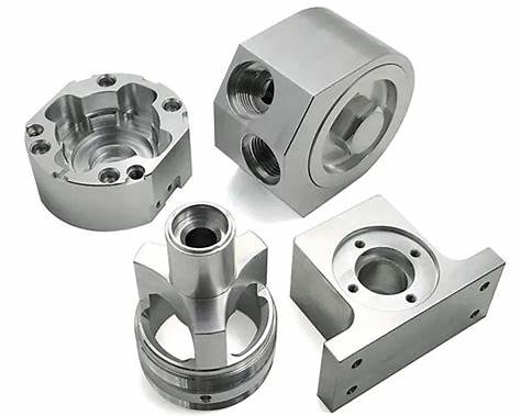
Weldment and finishing data for the combined quotation
Provide both the welded fabrication definition and the finished-part requirements. Identify every machined interface, final datum, minimum remaining section and surface requirement. State which stock dimensions are fixed and which remain open to a manufacturability proposal.
Include the proposed welding, treatment and machining order if it is already constrained. Where the route is open, request a sequence proposal and the assumptions supporting the allowance. An extra-stock quotation without a locating concept leaves an important part of the work undefined.
Specify the requested evidence: as-welded stock map, first-operation references, final dimensional report and any required weld inspection. If a development frame or sacrificial trial is needed, make its purpose and acceptance owner clear in the scope.
The standards and tolerances reference can support discussion of the drawing. The supplied product documents must still establish the actual limits. Retain approved changes to pads, fixtures and process order with the relevant revision. That makes a successful trial useful for repeat production rather than an isolated result dependent on undocumented shop adjustments.
FAQ
Is machining allowance the same as welding shrinkage compensation?
No. Shrinkage compensation changes the fabrication arrangement to address expected movement, while machining allowance supplies removable material around a finishing envelope. They can interact, but they require different references and evidence. State which quantity a dimension represents. A pre-set assembly can still lack cleanup stock at one pad, and a heavily oversized pad can still end up incorrectly positioned if the locating and welding sequence are unresolved.
Can a low mounting pad be accepted if the other pads clean up?
Only if the released design permits that contact condition or an approved disposition changes it. The importance depends on the actual interface, load path and assembly requirements. Do not treat the number of cleaned pads as an acceptance rule. Map the low region, determine its relation to the specified plane and minimum section, and obtain the relevant engineering disposition before machining the other pads lower to match it.
Should all stock be removed in the first machining setup?
That depends on stiffness, reference development and the approved route. A first stage may establish stable references or remove bulk material before finishing, while another part may be suitable for a single setup. Evaluate the sequence against released geometry and remaining section rather than adopting a universal rule. If staged machining is proposed, identify the intermediate condition and demonstrate the final part after the required release and downstream operations.
Conclusion
Effective allowance leaves enough material around the right final envelope, with a locating and restraint plan that remains valid through finishing. Inspect the welded input, the machined interfaces and the released assembly as distinct stages. A clean face alone does not establish the required relationships.
Use a representative trial to connect stock placement with actual fabrication variation. Preserve the successful sequence and its boundaries, including any treatment and release stages. When a pad fails to clean up, diagnose whether the cause is missing material, datum transfer or movement before adding stock indiscriminately.
For a combined fabrication and machining review, upload the weldment CAD, final interfaces and proposed allowance requirements. Include the acceptance state and minimum sections so 6CProto’s DFM review can assess a complete route to the finished assembly.
{“@context”: “https://schema.org”, “@type”: “FAQPage”, “mainEntity”: [{“@type”: “Question”, “name”: “Is machining allowance the same as welding shrinkage compensation?”, “acceptedAnswer”: {“@type”: “Answer”, “text”: “No. Shrinkage compensation changes the fabrication arrangement to address expected movement, while machining allowance supplies removable material around a finishing envelope. They can interact, but they require different references and evidence. State which quantity a dimension represents. A pre-set assembly can still lack cleanup stock at one pad, and a heavily oversized pad can still end up incorrectly positioned if the locating and welding sequence are unresolved.”}}, {“@type”: “Question”, “name”: “Can a low mounting pad be accepted if the other pads clean up?”, “acceptedAnswer”: {“@type”: “Answer”, “text”: “Only if the released design permits that contact condition or an approved disposition changes it. The importance depends on the actual interface, load path and assembly requirements. Do not treat the number of cleaned pads as an acceptance rule. Map the low region, determine its relation to the specified plane and minimum section, and obtain the relevant engineering disposition before machining the other pads lower to match it.”}}, {“@type”: “Question”, “name”: “Should all stock be removed in the first machining setup?”, “acceptedAnswer”: {“@type”: “Answer”, “text”: “That depends on stiffness, reference development and the approved route. A first stage may establish stable references or remove bulk material before finishing, while another part may be suitable for a single setup. Evaluate the sequence against released geometry and remaining section rather than adopting a universal rule. If staged machining is proposed, identify the intermediate condition and demonstrate the final part after the required release and downstream operations.”}}]}