

Explore CNC Milling, Turning & EDM
A cavity revealed by a finishing pass may have existed inside the magnesium stock before the cutter reached it. Another surface pit may come from local tearing, an inclusion or damage during a later operation. Treating every opening as a feed-rate problem can waste trials and leave the actual stock condition unresolved.
Magnesium machining porosity needs an investigation that preserves the distinction between an internal discontinuity exposed by machining and damage created at the surface. Start with the product form, material identity and feature location. A cast near-net shape and a wrought blank do not carry the same manufacturing history.
This guide focuses on the evidence needed for that attribution and for product acceptance. It does not provide universal pore-size limits or assume that every cavity is cosmetic. Position relative to a seal, thread, loaded ligament or visible surface determines the engineering consequence.
Include stock form and acceptance zones in the CNC-machining review. The supplier needs to know whether the drawing permits an exposed discontinuity, requires internal inspection or prohibits repair. Those decisions cannot be inferred reliably from a general material designation or a photograph taken after the defect has been blended away.
How does starting stock affect magnesium machining porosity?
Trace the product form before changing cutting conditions.
A cast component and a wrought blank have different processing histories, so identify alloy, condition, source and stock location before deciding whether machining exposed a discontinuity or created surface damage.
Preserve the material certificate and its link to the blank. Record whether the component began as a casting, extrusion, forging, plate or another form. A similar alloy name is not enough to establish an equivalent structure or acceptance specification.
Luxfer's Elektron WE43B information identifies that product as a casting alloy. Its listed properties and conditions belong to that product and should not be applied automatically to a wrought item with a related designation.
Review machining allowance against the starting geometry. Removing a casting’s surface can expose a different internal region, while stock orientation and prior processing matter for another product form. These observations guide investigation; they do not prove that any particular supplied blank is defective or that wrought stock is free of internal discontinuities.
Porosity exposed by machining
Record the opening before additional cutting or polishing changes it. Note its position, apparent size, shape, distribution and relation to the cutting path. Preserve close images with a scale and a broader view that locates the feature on the component.
A subsurface cavity can become visible when the tool removes its covering material. Its appearance after a cut establishes when it was revealed, not when it formed. Distinguish that sequence from tearing or smearing that follows the cutting action and may change with tool condition.
An inclusion or preparation artifact can also resemble a pore in an image. Avoid a definitive metallurgical label until the method supports it. Compare representative sections or internal examination where necessary, using identified samples and a preparation method that preserves the feature.
If another cut is proposed as an investigative step, obtain disposition approval first. It removes evidence and dimensional margin. Record the amount and location of material removed, then compare the new surface without assuming that disappearance of the opening establishes acceptable remaining stock.
Cosmetic and functional acceptance zones
Divide the component by consequence rather than assigning one limit to every surface. A shallow visible opening on a nonfunctional exterior may raise an appearance question, while a similar indication on a seal land, thread flank or narrow loaded section can affect function.
Identify each zone on the drawing or controlled inspection plan. Define whether acceptance concerns isolated opening size, connected discontinuities, remaining wall, leakage or another product requirement. These quantities answer different questions and should not be substituted for one another.
Do not assume that a coating can make an unacceptable cavity acceptable. The surface-finishing route may change appearance or reveal a defect differently, but it does not by itself demonstrate structural integrity or a qualified seal.
Review any proposed filler, impregnation or blending with the responsible engineer. A repair can alter dimensions, chemistry, adhesion or service behavior and requires a defined approval route. Cosmetic concealment without an accepted repair specification destroys useful evidence and can transfer an unresolved problem into the final assembly.
Inspection and supplier disposition
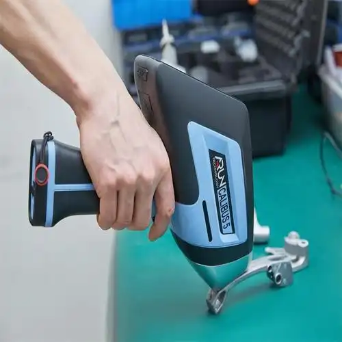
Choose inspection to answer the unresolved question. Visual examination describes the accessible surface; a section can reveal local structure; radiography or CT may investigate internal discontinuities. No method automatically establishes every required characteristic or the cause of every indication.
Nikon's industrial CT information describes casting examination for porosity, shrinkage and foreign material. For a particular magnesium component, verify that the selected scan and interpretation can resolve the relevant features through the actual geometry. A generic voxel-size claim is not a complete detection guarantee.
Keep supplier containment and engineering disposition traceable. Identify affected stock lots, casting identities where available, process batches and machined parts. A clean replacement part does not establish the extent of the original population.
The disposition record should distinguish accepted material, approved repair, further examination and rejection. Preserve the indication and its location before rework. When attributing the cause, compare stock evidence and machining evidence rather than treating whichever supplier handled the part last as responsible by default.
Comparing cast, billet and forged supply routes
Compare the actual product forms rather than creating a universal ranking of magnesium grades. The starting route determines which specification, certificate and inspection evidence are relevant. Bulk property values alone cannot establish whether a particular blank contains a discontinuity at the critical feature.
Luxfer's forging-alloy information distinguishes direct-chill cast billet supplied for forging from the subsequent forged product. This is an important procurement boundary: material suitable as forging feedstock is not automatically the same as a finished forged blank.
| Supply route | Evidence to preserve | Machining investigation question |
|---|---|---|
| Near-net casting | Alloy, condition, casting identity | Which internal region did machining expose? |
| Billet for further processing | Intended route and supplied condition | Was the specified transformation completed? |
| Forged or extruded blank | Product-form specification and orientation | Does the indication relate to stock or surface damage? |
Use grade-specific data only within its stated form and condition. A minimum property from a separately prepared specimen cannot be treated as a direct measurement of the remaining ligament around an observed cavity in the actual component.
Investigating openings on a newly machined seal land
Consider a hypothetical magnesium housing with several openings visible after its seal land is finish-machined. Preserve the part before another pass. Map the openings relative to the seal contact band, stock geometry and toolpath, and record tool identity and observed cutting condition.
Compare nearby surfaces and identified parts from the same stock population. If available, examine an unmachined or intermediate specimen using a method selected for the suspected internal feature. A repeated location in cast geometry suggests an investigation route, but does not alone establish the mechanism.
Review whether surface tearing, recut debris or an inclusion could explain the appearance. Use appropriate examination to distinguish the candidates rather than deciding from one low-resolution image. Keep the evidence collected before cleaning separate from that collected after an approved preparation step.
Disposition the seal land against the product’s requirements, including the assembled seal test where specified. A pore count on the surface cannot prove a connected leak path, and absence of immediate leakage does not automatically resolve another applicable strength or durability requirement.
Limits of internal images and local sections
An inspection image is evidence produced by a method with a defined scope. Scan settings, geometry, material thickness, reconstruction and interpretation influence what can be detected. A section shows one plane and can miss a nearby connected feature.
ASTM E1814's published scope distinguishes CT examination practice from the separate requirements controlling casting acceptability. Specifying a scan method therefore does not supply the product’s pore limits or release rule. Agree both the examination and the acceptance criteria.
ASTM E2869's digital-reference-image scope concerns magnesium casting radiographic interpretation and includes contractual personnel-qualification considerations. Its reference images do not automatically become an acceptance grade for every feature, nor should a film, digital projection and CT result be treated as interchangeable evidence.
Record detection limits and any inaccessible or uninterpretable regions in the report. A statement that no indication was detected should remain tied to the actual examination conditions. Do not translate it into a claim of zero porosity throughout the component unless the evidence and required definition genuinely support that conclusion.

Stock and defect requirements on the component drawing
State the alloy, product form, condition and governing material specification. Mark functional inspection zones, any required internal examination and the approved acceptance criteria. Specify whether repair is prohibited or requires written engineering disposition.
Define dimensions in the accepted final state and identify any critical remaining wall or ligament. For features produced through the CNC-milling route, connect the stock allowance to the finished geometry so inspection locations remain meaningful after material removal.
Use the standards and tolerances reference as context while retaining project-specific discontinuity requirements in the released documents. A general surface-finish callout does not define permitted cavities, and a material certificate does not replace any required part-level examination.
Keep changes in stock source, product form, repair route and critical machining allowance visible in change control. Those changes can alter which internal regions reach the finished surface. The manufacturing record should allow the next investigation to connect a part back to its starting material and process rather than restarting from an unidentified photograph.
FAQ
Does switching from cast to wrought stock guarantee a pore-free surface?
No. It changes the manufacturing route and may change the likely discontinuities, properties, orientation and cost, but it does not certify a particular blank. Confirm the exact alloy, form, condition and applicable inspection requirements. Review the design consequences and validate the finished component rather than treating wrought as a universal quality grade. Preserve supply traceability and the required examination evidence for whichever route is selected.
Can an acceptable leak test override a surface porosity rejection?
Only if the governing product requirements and authorized disposition permit that decision. A leak test addresses its defined fluid, pressure, temperature and duration. It may not resolve appearance, structural or contamination requirements associated with the same indication. Compare each applicable acceptance criterion and preserve the test conditions. A successful functional test can be useful evidence, but it should not silently replace an explicit drawing restriction or an untested service condition.
Should extra machining be used to remove every exposed pore?
Not without an engineering disposition. Another pass may remove an opening, reveal a larger internal cavity or reduce a critical wall below its requirement. Record the original condition and review available dimensional margin before altering the part. If additional machining is approved, inspect the resulting geometry and apply the required discontinuity and functional checks again. Disappearance from one surface does not establish that the remaining component meets every requirement.
Conclusion
Attribute an opening only after connecting its appearance with the starting stock, machining sequence and suitable examination evidence. Keep stock discontinuities, inclusions and cutting damage as separate hypotheses until the investigation supports a conclusion. Product acceptance then follows the affected feature’s requirements, independently of which process first revealed the condition.
Send 6CProto the model and drawing for a quotation, with alloy, product form, material condition, critical zones and permitted repair policy. Include any internal-examination or sealing requirements so the proposed supply route can be assessed against the accepted final component.
{“@context”: “https://schema.org”, “@type”: “FAQPage”, “mainEntity”: [{“@type”: “Question”, “name”: “Does switching from cast to wrought stock guarantee a pore-free surface?”, “acceptedAnswer”: {“@type”: “Answer”, “text”: “No. It changes the manufacturing route and may change the likely discontinuities, properties, orientation and cost, but it does not certify a particular blank. Confirm the exact alloy, form, condition and applicable inspection requirements. Review the design consequences and validate the finished component rather than treating wrought as a universal quality grade. Preserve supply traceability and the required examination evidence for whichever route is selected.”}}, {“@type”: “Question”, “name”: “Can an acceptable leak test override a surface porosity rejection?”, “acceptedAnswer”: {“@type”: “Answer”, “text”: “Only if the governing product requirements and authorized disposition permit that decision. A leak test addresses its defined fluid, pressure, temperature and duration. It may not resolve appearance, structural or contamination requirements associated with the same indication. Compare each applicable acceptance criterion and preserve the test conditions. A successful functional test can be useful evidence, but it should not silently replace an explicit drawing restriction or an untested service condition.”}}, {“@type”: “Question”, “name”: “Should extra machining be used to remove every exposed pore?”, “acceptedAnswer”: {“@type”: “Answer”, “text”: “Not without an engineering disposition. Another pass may remove an opening, reveal a larger internal cavity or reduce a critical wall below its requirement. Record the original condition and review available dimensional margin before altering the part. If additional machining is approved, inspect the resulting geometry and apply the required discontinuity and functional checks again. Disappearance from one surface does not establish that the remaining component meets every requirement.”}}]}