

A wire cut profile can be dimensionally correct and visually smooth while its near surface condition still needs evaluation. Wire EDM recast layer refers to material that melts during discharge machining and resolidifies on the cut surface. Its significance depends on the alloy, discharge conditions, subsequent finishing and the function of that particular surface.
For a highly loaded component, surface integrity should be a stated acceptance requirement rather than an assumption inferred from the number of skim passes. This guide separates roughness, altered material and dimensional accuracy, then connects inspection and removal to a traceable process. It does not assign a universal acceptable layer thickness or presume that all EDM surfaces need the same treatment.
What does wire EDM recast layer actually describe?
It is resolidified material on the cut surface.
Distinguish the recast material from surface texture and other thermally affected regions; a smooth profile or good dimensional result does not establish the complete near surface condition.
Discharge machining removes material through localized electrical discharges in a controlled dielectric environment. Not all affected material is expelled, and the resolidified region can differ from the original substrate. Its distribution need not be uniform along a complex cut, particularly where flushing and cutting conditions vary.
Makino’s explanation of recast formation in ram EDM illustrates the melting and resolidification principle; the wire cut result still requires its own process evidence. The relevant engineering question is not whether a generic description calls EDM precise, but what the released process leaves on the specified alloy and feature. Identify which surfaces are discharge machined, which remain as supplied and which receive subsequent removal. Keep the term recast separate from ordinary visible tool marks.
Show the section definition when using layer terminology in a report. Different observers can otherwise group resolidified material and adjacent altered regions differently while reporting apparently comparable results afterward.
Rough and skim cut differences
A rough cut establishes the initial separation and profile, while later skim cuts can refine geometry and surface condition under a different discharge strategy. The outcome depends on the machine technology, material, wire, dielectric, flushing and programmed conditions. Pass count alone is not a transferable specification across all systems.
Makino’s wire EDM process technology information illustrates that real cutting conditions, including poor flushing and changing section, affect process behavior. Its published capability statements describe a particular technology under stated conditions; they should not be converted into a generic guarantee for a different machine or component.
State the final surface requirement and ask for evidence from the proposed sequence. If a supplier proposes fewer passes or a different generator setting, determine which qualification results support equivalence. A reduced cycle time may be acceptable, but the dimensional result cannot be the sole basis when the drawing also limits altered surface material. Preserve the actual cut sequence with the sample identification.
Keep the final finishing condition distinct from the rough cut settings. A record that identifies only the first cut cannot support a claim about the surface delivered after later passes.
Fatigue sensitive applications
A surface exposed to repeated stress may be sensitive to local defects, altered material or residual stress. This does not mean every recast layer causes failure, nor that every wire EDM feature is fatigue critical. Identify the load path, local stress concentration and environment before assigning the level of evaluation.
Makino’s advanced EDM process discussion for aerospace is useful background for why demanding applications distinguish surface integrity from shape. It is not evidence of a customer’s approval, an aerospace qualification or a capability claim for a different supplier.
The responsible design authority should identify critical surfaces and their acceptance requirements. A low stressed clearance slot may justify a different treatment from a highly loaded internal corner. Include corrosion or environmental exposure where it changes the concern. Review the complete part condition: heat treatment, prior machining, EDM sequence and subsequent finishing can all matter. Avoid specifying blanket removal without considering whether the removal method can preserve the functional geometry.
Identify the direction of service loading relative to the cut feature. A critical surface designation should follow the actual stress and environment review rather than the machining process name alone.
Choose an inspection and removal plan
Decide what evidence is needed to evaluate the affected region. Metallographic sections can reveal local structure, while other methods may evaluate cracks or surface discontinuities under an application specific procedure. A surface roughness trace measures texture; it cannot by itself measure recast thickness or establish the absence of microcracks.
The Mitutoyo surface measurement guide provides the measurement context for texture, which should be specified separately. Define section locations and preparation so the laboratory does not examine only the easiest accessible straight portion. Corners, entry or exit regions and changing section may deserve attention based on the process and load path.
If removal is required, choose a method that reaches the critical surface and has a measurable endpoint. Polishing a visible face may leave an internal feature untouched. Conversely, aggressive finishing can round an edge or enlarge a slot. Coordinate the removal and inspection plan within the EDM component review, with explicit responsibility for approving the final surface condition.
Agree how sample preparation avoids obscuring the region of interest. Poor section preparation can remove, smear or damage evidence and make an apparent absence difficult to interpret with confidence.
Process sequence and access diagram
Map the process on a sectioned drawing before releasing stock allowances. Show the starting condition, rough cut, skim strategy, any subsequent material removal and final inspection. This exposes whether a critical surface remains accessible after the part is separated or assembled.
For a narrow slot, the sequence might be material preparation, rough cut with allowance, controlled finishing passes, a defined finishing operation if required, cleaning and final verification. That sequence is illustrative; each stage needs a validated purpose. Do not add polishing simply because it sounds protective if the tool cannot reach the wall uniformly.
An earlier turning operation may establish the datum used for the EDM setup. Preserve that datum through release and inspection, or define how it transfers to a new reference. The ASME drawing framework supports clear feature relationships, but it does not prescribe a universal EDM surface limit. Link the finishing allowance to both the dimensional tolerance and the required surface integrity evidence.
If a later operation removes a datum, plan the inspection reference before that stage. The final surface must remain measurable against the drawing even after temporary setup features disappear.
Dimensional and surface verification matrix
Use separate rows for shape, texture and altered material. Each measurement should name a location and a method, with acceptance criteria from the drawing or approved process specification. A report that says only “surface checked” cannot establish which requirement was evaluated.
| Characteristic | Evidence | Important limitation |
|---|---|---|
| Profile and size | Appropriate dimensional measurement | Does not establish near surface metallurgy |
| Surface texture | Defined roughness measurement | Does not prove altered layer depth |
| Recast or affected region | Qualified section examination | Represents examined locations and sampling plan |
| Crack assessment | Application appropriate inspection procedure | Detection capability must suit the defect concern |
| After removal | Surface and dimensional reinspection | Finishing can change edges and local size |
Coordinate these items through the inspection requirements. Agree whether testing consumes a production part, a witness coupon or a representative qualification sample, and explain how that specimen relates to the actual critical surface.
Record the number and locations of examined sections with the report. A maximum observed value is bounded by that sampling plan, not automatically the maximum anywhere on the component.
Trial evidence and acceptance boundary
Consider a hypothetical spring component with a wire cut slot and a highly loaded root. Assume the design authority requires evaluation of the final slot root and walls, but has not assigned a numerical altered layer limit. The first task is to resolve that acceptance requirement, not to invent a general threshold.
Prepare representative samples using the proposed material condition, section thickness, wire cut sequence and final finishing. Examine the designated locations and measure the final slot geometry. If the root is inaccessible to the proposed finishing tool, a favorable result from an open straight wall does not prove that the root meets the same condition.
Compare any revised pass sequence with the qualified baseline using the same inspection plan. A lower roughness value is useful evidence for texture, but cannot alone establish less recast material. Document the observed boundary of the trial: alloy, machine process, geometry and sample locations. Expansion to a different material or substantially different section requires a reasoned review rather than an automatic carryover.
Where a witness coupon is used, explain why its thickness and flushing conditions represent the critical feature. Similar material alone does not make an open coupon equivalent to a slot.
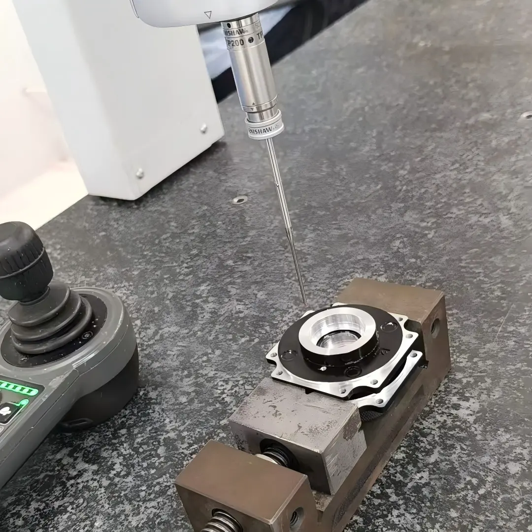
Feature data required for a specialist process RFQ
An RFQ for a critical EDM feature needs more than a profile file. Supply the material designation and condition, section thickness, start hole constraints, critical radii, dimensional datums and the surfaces subject to special integrity requirements. Identify any features where edge rounding or additional material removal is restricted.
State the inspection method or the approval process for selecting it. If the specification requires a maximum altered layer or absence of particular discontinuities, include the exact requirement and applicable method. Do not replace a missing acceptance definition with the phrase “aerospace quality” or a requested number of skim passes.
Explain whether the scope includes destructive qualification, production inspection, post EDM finishing and final cleaning. The Mitutoyo surface measurement resources are relevant to texture planning but do not cover every metallurgical concern. Keep the process evidence and dimensional report tied to the same drawing revision, and require approval when material, discharge strategy or subsequent finishing changes the qualified surface condition.
Identify who authorizes an alternate process and what evidence must accompany it. Approval should address the final surface requirement, not merely the supplier preference for fewer operations or passes.
FAQ
Do more skim passes always remove the recast layer?
Additional passes can improve the result under an appropriate process, but pass count is not a universal measure of the final altered surface. The discharge strategy, material, wire, flushing and geometry also matter. If a layer limit is important, define the acceptance method and qualify the actual sequence on representative surfaces. Do not infer complete removal from the words finish cut or from a visually smooth surface without evidence that addresses the stated requirement.
Can roughness measurement replace metallographic inspection?
No. Roughness describes surface texture under a defined measurement method, while a section examination can reveal aspects of the material below the surface. They answer different questions. A smooth trace does not establish recast depth, and a section at one location does not characterize the texture of every functional surface. Use the measurements required by the application and identify their locations and limitations. Avoid treating a single attractive number as a complete surface integrity report.
Is polishing after wire EDM always necessary?
No blanket rule applies. The need depends on the material, load path, environment, final surface requirement and qualified EDM process. Polishing can also alter slot size, edge geometry or a critical radius, and it may not reach an internal feature uniformly. If it is required, specify the surfaces, allowable removal and verification endpoint. The finished component should be rechecked for both geometry and the surface condition that justified the operation in the first place.
Conclusion
Treat recast material, roughness and dimensional accuracy as separate characteristics of the finished EDM feature. Define which surfaces matter, select evidence that can evaluate them, and preserve the relationship between that evidence and the actual cut and finishing sequence. A pass count or a smooth appearance is not a substitute for an application specific acceptance requirement.
Where removal is necessary, verify access and dimensional consequences before selecting the method. Qualify representative critical locations, then identify which changes require reapproval. For a defined component review, send the model, material condition and surface integrity requirements for quotation. An explicit inspection boundary gives manufacturing a clear target and prevents a dimensional success from being mistaken for proof of every near surface property.
{“@context”: “https://schema.org”, “@type”: “FAQPage”, “mainEntity”: [{“@type”: “Question”, “name”: “Do more skim passes always remove the recast layer?”, “acceptedAnswer”: {“@type”: “Answer”, “text”: “Additional passes can improve the result under an appropriate process, but pass count is not a universal measure of the final altered surface. The discharge strategy, material, wire, flushing and geometry also matter. If a layer limit is important, define the acceptance method and qualify the actual sequence on representative surfaces. Do not infer complete removal from the words finish cut or from a visually smooth surface without evidence that addresses the stated requirement.”}}, {“@type”: “Question”, “name”: “Can roughness measurement replace metallographic inspection?”, “acceptedAnswer”: {“@type”: “Answer”, “text”: “No. Roughness describes surface texture under a defined measurement method, while a section examination can reveal aspects of the material below the surface. They answer different questions. A smooth trace does not establish recast depth, and a section at one location does not characterize the texture of every functional surface. Use the measurements required by the application and identify their locations and limitations. Avoid treating a single attractive number as a complete surface integrity report.”}}, {“@type”: “Question”, “name”: “Is polishing after wire EDM always necessary?”, “acceptedAnswer”: {“@type”: “Answer”, “text”: “No blanket rule applies. The need depends on the material, load path, environment, final surface requirement and qualified EDM process. Polishing can also alter slot size, edge geometry or a critical radius, and it may not reach an internal feature uniformly. If it is required, specify the surfaces, allowable removal and verification endpoint. The finished component should be rechecked for both geometry and the surface condition that justified the operation in the first place.”}}]}