

Facing toward a spindle center changes the cutting diameter continuously, so a fixed rotational speed and a constant surface speed mode produce different behavior. In the Haas lathe convention used here, G96 selects constant surface speed and G97 selects fixed spindle speed in rpm. The G96 vs G97 decision must also consider maximum speed limits, workholding and the actual machine’s interpretation.
The calculations below explain the relationship; they are not executable turning instructions or recommended cutting parameters. Verify the installed control, units, tool position and approved setup before applying any mode. A mathematically correct speed can still be unsuitable for the chuck, workpiece, machine or operation.
What changes between G96 vs G97 in turning?
G96 controls surface speed; G97 controls spindle rpm.
On the referenced Haas lathe, constant surface speed changes rpm with cutting diameter, while fixed rpm leaves surface speed to vary; both require an approved setup and limits.
Surface speed is proportional to diameter times rotational speed. At a fixed rpm, a smaller diameter has a lower surface speed. At a fixed target surface speed, the commanded rpm must rise as diameter decreases. Haas’s G96 constant surface speed reference and G97 fixed speed reference define the relevant controller functions.
Confirm whether the diameter information and units used by the control match the intended setup. Tool offsets and coordinate conventions matter because the calculation depends on where the cutting point is relative to the spindle axis. Do not infer physical speed behavior from the code name alone, and do not copy a surface speed number into an rpm command without converting the quantity.
Check the distinction between a commanded speed and the speed actually reached during a changing diameter cut. Machine acceleration and limits can affect the process beyond the simple steady calculation.
Spindle speed limits
A constant surface speed request needs an appropriate maximum rotational limit and a setup that is suitable throughout the motion. The machine’s maximum rpm is not automatically an acceptable process limit for the workpiece. Workholding, balance, unsupported length and the specific operation can impose lower restrictions.
The applicable Haas lathe programming manual should be used to verify how that control establishes and retains speed limits. Do not assume a limit is present because a previous program used one, or that another controller uses identical syntax or persistence. Review the limit at program entry and restart points.
Check the actual workholding documentation and approved setup as well. A long slender blank, irregular stock or a changed gripping condition may need a different assessment even when the final part is unchanged. Keep speed limitation separate from cutting speed selection: a limit prevents an excessive rpm request, but it does not establish that the chosen cutting conditions will produce an acceptable or stable cut.
A change in jaw position or gripping length can alter the permitted setup. Review workholding again rather than treating the previous rpm limit as a permanent property of the part.
Facing toward the center
As the theoretical cutting diameter approaches zero, the rpm required for a fixed nonzero surface speed rises without bound in the simple formula. A real machine and approved setup must impose limits. The process near the center therefore cannot be understood by extrapolating a single surface speed value indefinitely.
Review the facing path, insert geometry, tool position and center condition. At a speed limit, actual surface speed decreases as diameter continues to shrink. That is expected from the relationship, not proof that the control failed to maintain its command. The result at the center still needs process evaluation.
Sandvik’s turning formulas provide the units and relationship used in the calculation. Their use does not validate a particular machine instruction. Include entry, center approach and retract in the verification, and distinguish a toolpath that crosses the theoretical center from one that ends before it. Any mode transition should follow the actual control documentation and the approved process rather than a generic facing recipe.
Define the relevant center condition in the process record. Theoretical zero diameter arithmetic does not describe every practical tool contact, tool geometry or end condition of a facing operation alone.

Confirm controller and machine behavior
Identify the exact control and machine configuration before selecting the mode. Check units, interpretation of the speed value, limiting behavior and what happens when a mode changes. A mill code reference is not a substitute for a lathe manual, even when the number looks familiar.
Verify the relationship between the programmed coordinate and the cutting diameter, including tool offsets and relevant transformations. In a compound setup, confirm which spindle and tool position the command affects. A controller option or machine builder implementation can change the required sequence.
Haas’s machine safety guidance is useful background for machine operation, but the actual lathe owner’s approved procedures and lathe documentation govern prove out. For a turning process review, separate the finished part requirement from the selected speed mode. The drawing defines diameters and surfaces; the verified setup establishes how the particular machine will produce them within its physical and operational constraints.
If the machine has multiple spindle arrangements, identify which system the instruction affects. Familiar code text can conceal a configuration assumption that is absent from a simple training example elsewhere.
Units and controller compatibility checklist
Use a compatibility checklist to prevent quantity and state errors. The same S value can describe different quantities under different modes, so a reviewer must identify the selected mode before interpreting the number. Include the initial state and any restart assumptions.
| Check | G96 concern | G97 concern |
|---|---|---|
| Units | Surface speed unit must match the control | Speed is rpm under the referenced convention |
| Diameter | Changes the requested rpm | Changes actual surface speed |
| Speed limit | Must be deliberately established and verified | Requested rpm must suit the setup |
| Mode transition | Review resulting command and limits | Define the intended fixed speed explicitly |
| Workholding | Check the full reachable speed range | Check the selected rpm and operation |
Keep the machine process record coordinated with the acceptance requirements. A speed mode choice can affect finish and stability, but it does not replace the dimensional and surface checks required for the part.
Record how the limit is established after a restart or program transfer. A value written in a setup note does not prove that the controller has that limit active during motion.
Worked calculation or annotated toolpath example
Assume a hypothetical metric example with a target surface speed of 150 m/min. Use n = 1000Vc/(pi D), with D in millimeters. At a diameter of 50 mm, the calculated speed is approximately 955 rpm; at 25 mm it is approximately 1,910 rpm. The diameter halves and the required rpm doubles.
Now assume an illustrative approved limit of 2,000 rpm. At 10 mm diameter, the unrestricted calculation would request approximately 4,775 rpm, so the limit would prevent that request from being achieved. At 2,000 rpm and 10 mm diameter, actual surface speed is pi x 10 x 2,000/1000, approximately 62.8 m/min.
These numbers illustrate the relationship and do not recommend a tool, material speed or safe spindle limit. A real limit requires the machine and setup assessment. If the process uses fixed 955 rpm instead, the surface speed at 25 mm would be approximately 75 m/min. Review the expected range before deciding which mode suits the actual operation.
Keep rounding consistent with the intended review precision. The example uses approximate rpm values, so downstream arithmetic should not imply a tighter numerical certainty than the original assumptions support here.
Simulation and first-part verification checks
Simulation and program review should show the expected spindle behavior alongside tool motion. A nominal path display may not model speed limits or acceleration, so confirm which aspects the verification environment actually represents. Review the released program and the active setup rather than only the CAM operation’s name.
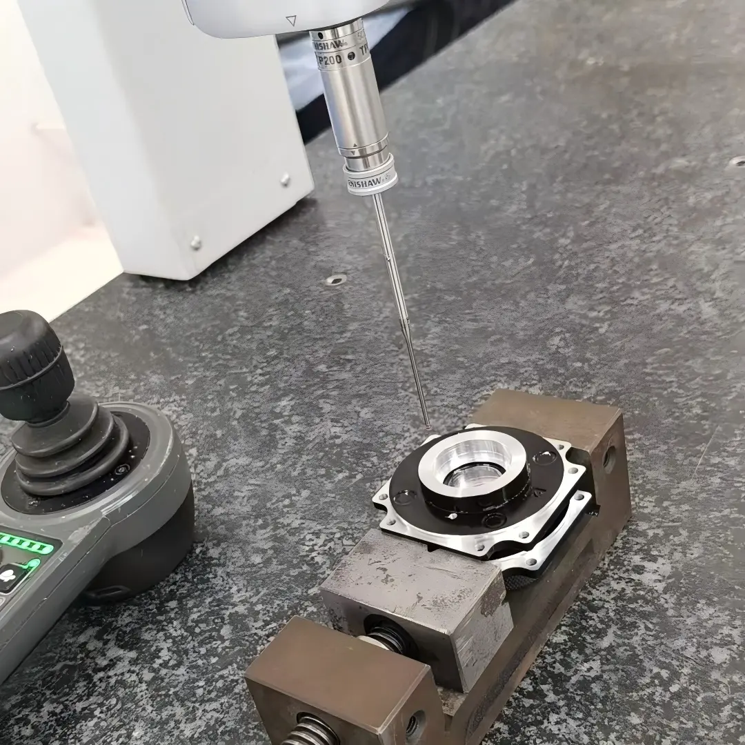
During the approved first part process, inspect size, surface texture and any evidence of unstable cutting. Relate observations to diameter and operation, because a surface speed or limiting transition can occur during a single pass. The Mitutoyo surface measurement guide explains why a defined texture measurement is more useful than a general shiny appearance check.
Record actual process conditions where the verification procedure requires them. A good result at one diameter does not establish the full facing range or a different workholding condition. For components later receiving milled features, preserve the turned datums and document any shape or surface changes that could affect the next setup. The two operations need coordinated acceptance, not a presumed benefit from one speed mode.
Inspect the surface near any limiting transition when it is relevant to function. A measurement made only at the largest diameter may miss a different condition closer to the center region.
Process documentation and handoff notes
Document the chosen mode, units, intended speed quantity, applicable rpm limit and machine configuration in the setup record. Include the workholding and tool information that support the decision. A comment saying “CSS on” is insufficient when the actual command, limit or units remain ambiguous.
Identify mode changes and expected behavior at entry, facing, center approach and subsequent operations. Review restart conditions so a skipped setup block cannot leave the program relying on an inherited speed or limit. If the machine or postprocessor changes, verify the interpretation again rather than transferring a familiar code sequence unexamined.
Where a part requires additional machining orientations, keep the turning record distinct from later setup conventions. The final process package should connect the program revision and first part evidence to the drawing revision. Changes in gripping, stock form or speed strategy need a deliberate review even if the final nominal diameter and material designation are unchanged.
Specify which changes trigger renewed review, including stock balance and workholding revisions. Keeping the same nominal code mode does not preserve the approval basis when the physical setup changes substantially.
FAQ
When is fixed rpm useful instead of constant surface speed?
Fixed rpm can be appropriate where the operation or control requires a defined rotational speed, or where the process is designed and validated around a limited diameter range. Constant surface speed can be useful when diameter changes substantially, but it requires suitable limits and setup verification. The choice depends on the tool, workholding, machine and operation. Do not select solely from a general preference for one mode or assume that a mode name establishes acceptable cutting conditions.
Does G96 guarantee constant cutting conditions?
No. It controls a surface speed relationship under the documented controller behavior, but actual conditions also depend on the speed limit, acceleration, engagement, tool condition and workpiece. Once the required rpm exceeds the approved limit, the target surface speed cannot be maintained as diameter decreases. Review the actual operating range and inspect the resulting part. A controller mode cannot independently establish stable cutting, dimensional accuracy or suitability for the workholding arrangement.
Can the same S value be reused when switching to G97?
Do not assume the quantity remains the same. Under the Haas lathe convention discussed here, G96 uses a surface speed value while G97 uses rpm. A number that was appropriate as one quantity may be inappropriate as the other. Verify the actual controller's transition behavior and explicitly establish the intended fixed speed according to the approved program. Review limits and setup conditions as well, rather than treating the mode change as a simple label replacement.
Conclusion
Choose the speed mode from the diameter range, operation and verified machine behavior. Constant surface speed changes the rpm request with diameter, while fixed rpm lets surface speed change. Neither choice removes the need for appropriate workholding, a suitable limit and a complete process review.
Keep the units and quantities explicit, check center approach behavior and verify transitions and restart conditions against the actual lathe documentation. First part evidence should confirm the required geometry and texture across the relevant operation, not only at one convenient diameter. For a component review, send the drawing, material condition and critical turned surfaces for quotation. A clearly defined part and setup boundary make the speed strategy reviewable without turning a calculation example into an unqualified machining instruction.
{“@context”: “https://schema.org”, “@type”: “FAQPage”, “mainEntity”: [{“@type”: “Question”, “name”: “When is fixed rpm useful instead of constant surface speed?”, “acceptedAnswer”: {“@type”: “Answer”, “text”: “Fixed rpm can be appropriate where the operation or control requires a defined rotational speed, or where the process is designed and validated around a limited diameter range. Constant surface speed can be useful when diameter changes substantially, but it requires suitable limits and setup verification. The choice depends on the tool, workholding, machine and operation. Do not select solely from a general preference for one mode or assume that a mode name establishes acceptable cutting conditions.”}}, {“@type”: “Question”, “name”: “Does G96 guarantee constant cutting conditions?”, “acceptedAnswer”: {“@type”: “Answer”, “text”: “No. It controls a surface speed relationship under the documented controller behavior, but actual conditions also depend on the speed limit, acceleration, engagement, tool condition and workpiece. Once the required rpm exceeds the approved limit, the target surface speed cannot be maintained as diameter decreases. Review the actual operating range and inspect the resulting part. A controller mode cannot independently establish stable cutting, dimensional accuracy or suitability for the workholding arrangement.”}}, {“@type”: “Question”, “name”: “Can the same S value be reused when switching to G97?”, “acceptedAnswer”: {“@type”: “Answer”, “text”: “Do not assume the quantity remains the same. Under the Haas lathe convention discussed here, G96 uses a surface speed value while G97 uses rpm. A number that was appropriate as one quantity may be inappropriate as the other. Verify the actual controller’s transition behavior and explicitly establish the intended fixed speed according to the approved program. Review limits and setup conditions as well, rather than treating the mode change as a simple label replacement.”}}]}