

Explore CNC Programming & Process Engineering Guides
A screw that stops turning has not necessarily clamped the assembly. It may have reached incomplete threads, contacted packed chips or touched the bottom of the hole. Increasing installation torque can conceal the real problem until a boss cracks or a joint loosens. Blind hole tap drill depth therefore needs three distinct definitions: the usable thread, the cylindrical predrill and the deepest drill tip position.
The drawing should protect the required engagement and the remaining material together. Manufacturing then selects a thread making process that fits inside that envelope. A single depth copied between the hole, tap and screw does not communicate this relationship. The following approach connects tool geometry, a dimensioned section and inspection evidence without assuming a universal number of extra thread pitches.
This is a feature specification problem rather than a tap drill diameter chart. Nominal thread size and pitch are necessary inputs, but neither determines the bottom allowance on its own. The selected tap, chip behavior, entry chamfer and available wall thickness all affect what can actually be made and verified.
Separate full thread and drilled depths
Full thread depth is the length that meets the specified thread form and tolerance, measured from the stated reference. Cylindrical drill depth is the length over which the predrill has its full diameter. Tip depth extends farther, to the deepest point cut by the drill. These dimensions may share a datum, but they describe different surfaces and must not be treated as synonyms.
A tap’s chamfered lead forms progressively deeper threads. Consequently, the lowest visible thread marks can extend beyond the fully formed thread that the screw may use. The SFS thread generation guide distinguishes cutting, forming and milling methods; their tool ends and clearance requirements differ. Establish the required functional engagement first, then ask the process planner to show the necessary tool envelope.
State whether a depth is a minimum usable length, a controlled interval or a maximum material removal. A minimum full thread requirement and a maximum tip depth can coexist. Their compatibility must be demonstrated with the chosen tooling rather than resolved by silently deepening the hole during production.
Drill point geometry at the bottom
The drill point leaves a tapered bottom below the cylindrical bore. For an ideal symmetrical conical point of included angle A and diameter D, the additional axial depth is h = D / [2 tan(A/2)]. This geometric relation describes the ideal cone; it does not establish the actual point shape of a split point or a special bottoming tool.
As a hypothetical calculation, D = 5 mm and A = 118 degrees give h approximately 1.50 mm. At 140 degrees, the same ideal cone is approximately 0.91 mm deep. A change in angle therefore changes the deepest material removal even when the cylindrical depth stays fixed. These values are geometry examples, not recommended drill specifications.
Check the tip envelope against the closest external surface, adjacent passage and any offset hole. A nominal wall thickness measured from the cylindrical end can miss the deepest penetration. For a feature made by CNC milling operations, show the relevant section and identify which bottom surfaces are functionally constrained before selecting the drilling sequence.
Tap lead and chip clearance
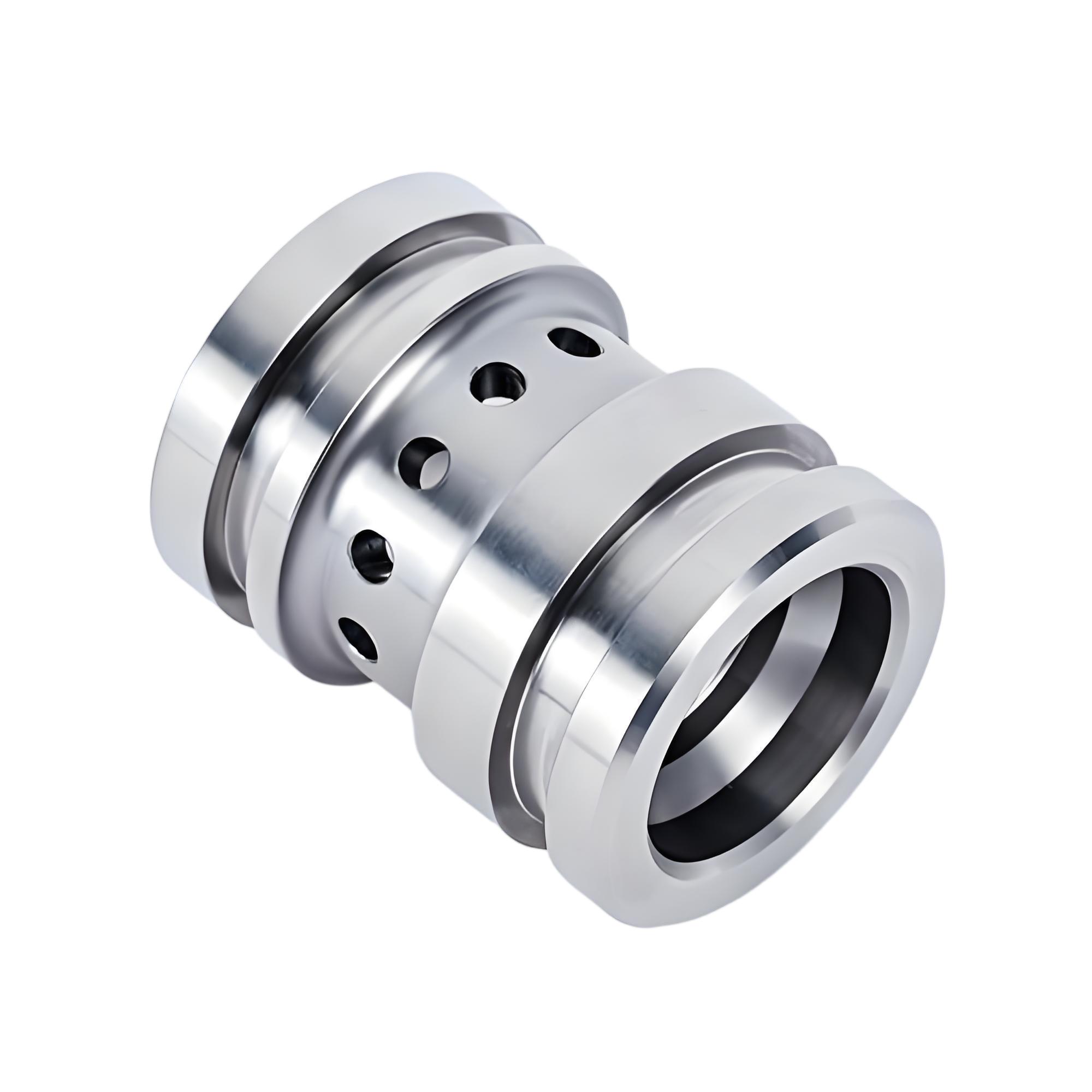
The tap lead needs axial room beyond the complete threads, while the cutting process needs a viable path for chips. These are related allowances, but one cannot stand in for the other. A shorter lead may reach closer to the bottom without solving chip packing, lubrication or reversal problems.
For blind cutting applications, select a tap construction appropriate to the material and chip direction. The manufacturer's process comparison explains why a spiral point construction that sends long chips forward can be unsuitable in a blind hole. Thread forming avoids cutting chips but requires compatible material and a different prehole specification. It still has a lead and an end clearance requirement.
Ask for the actual tool designation and geometry instead of approving an allowance called bottoming clearance. A controlled process sheet should connect programmed travel, lead length, predrill depth and the remaining bottom space. Keep chip evacuation in the discussion: Sandvik's drilling guidance treats coolant delivery and chip removal as contributors to hole quality, not merely cycle time accessories.
Dimension the usable engagement
Dimension engagement from the joint’s assembled condition. The screw must pass through the clamped stack and enter enough complete internal threads without contacting the bottom at the worst permitted combination of dimensions. Account for the screw end, washer arrangement, entry chamfer and any unthreaded length before assigning the working engagement.
Do not count every turn that can be inserted by hand as full engagement. The screw can enter a partially formed region and develop resistance that resembles tightening. Likewise, a plug gauge’s own end geometry may prevent it from reaching a specified full thread depth even when the thread is acceptable. The measurement plan needs to recognize those differences.
Use an explicit reference surface for each axial dimension. The public scope of ASME Y14.5 establishes a drawing language for communicating form, fit and function; it does not supply a universal blind tap allowance. Keep the product requirement on the drawing and the selected tool travel in the manufacturing plan. Review any proposal to reduce usable engagement as an engineering change.
A section that protects thread engagement and bottom wall
A section through the hole axis should show the entry treatment, minimum complete thread length, cylindrical bore end and deepest permitted tip. Add the nearest protected boundary. If that boundary is an offset hole, a second section or a three dimensional interference check may be needed to capture the closest approach.
For illustration, suppose the design requires 10 mm of complete thread in a hypothetical boss. Let the planner’s selected lead and operating clearance require another 3 mm of cylindrical bore, and let the ideal point allowance be 1.5 mm. The resulting tip position is 14.5 mm from the same reference, before evaluating tolerances. The 3 mm allowance is an assumed input for this example, not a general tap rule.
The useful review question is whether the maximum possible tip position preserves the minimum permitted wall. Put both limits on the section and evaluate the dimensional extremes. When the envelope does not close, alternatives include a different tool end, revised engagement, thread milling or a changed boss. Simply making the depth note less precise transfers an unresolved design conflict to manufacturing.
Comparing thread gauges, depth probes and sectioned samples
Select inspection by the characteristic that must be established. A depth probe, thread gauge and sectioned sample produce different evidence. A tool travel record supports process control, but does not independently prove the finished internal geometry or the absence of chips.
| Method | Useful evidence | Important limitation |
|---|---|---|
| Thread plug gauge | Thread acceptance under the selected gauge method | Gauge end can limit accessible depth |
| Depth probe | Contact depth at the probe location | Contact may occur on cone or debris |
| Sectioned trial part | Lead region and actual bottom geometry | Destructive and local to the section |
| Recorded machine travel | Programmed process position | Does not prove finished engagement |
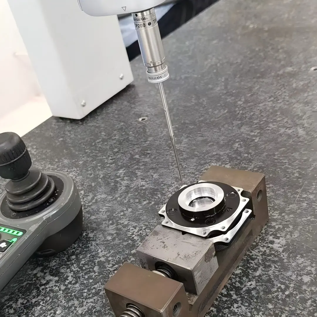
Fixture the component consistently when comparing depth observations. Renishaw’s metrology fixturing information describes repeatable setups for contact and vision inspection. For this feature, the practical objective is to preserve the datum and access direction so apparent depth changes are not caused by a tilted part. Agree which method controls acceptance before the first article arrives.
Prove screw clearance without confusing resistance with seating
Verify the complete thread requirement, predrill boundary, cleanliness and assembled screw clearance as separate items. A passing thread gauge does not establish adequate remaining wall, and a correct drill depth does not establish acceptable thread form. The report should identify each characteristic and the method used to evaluate it.
Trial assembly can expose bottoming, but use a controlled screw and stack rather than an arbitrary fastener from a bin. Record the relevant lengths and inspect for contact evidence. If a screw reaches its expected position only after unusually high resistance, investigate incomplete threads, contamination or local damage instead of treating the result as normal seating.
Inspect the predrill when process symptoms suggest a problem upstream of tapping. Sandvik's drilling troubleshooting guide separates size, vibration and tool related issues rather than assigning every failure to the following operation. Connect these checks to the agreed drawing and inspection requirements. Where wall integrity is critical, define the appropriate first article evidence rather than relying on thread acceptance alone.
Blind thread callouts needed for a machining quotation
The quotation package needs the thread designation, tolerance, minimum usable depth, entry chamfer, permitted bottom envelope and material condition. Include a section showing adjacent features and the smallest protected wall. A model containing a generic tapped hole is not enough when its cosmetic thread hides an unresolved bottom allowance.
Identify the screw and assembled stack if manufacturing is expected to assess engagement. State whether thread forming or milling is acceptable, whether the bottom must remain conical and whether chips or loose material create a functional concern. These choices affect tooling and inspection even when the nominal thread size remains unchanged.
For axially drilled features in turned components, preserve the relationship to the locating face and concentric features. Resolve contradictory model and drawing depths before release. Record any approved process alternative with its effect on the complete thread length and maximum penetration; an approval to change the manufacturing method should not become an implied approval to remove more material.
FAQ
Can a bottoming tap produce complete threads to the floor?
A bottoming construction can reduce the incomplete lead region, but it still has tool geometry and needs a suitable operating clearance. Its name does not establish the last usable thread position. Check the specific tool drawing, material and chip behavior, then demonstrate the required complete thread depth. If a nearly flat functional floor or exceptional engagement is necessary, evaluate a different process or feature design rather than assuming a bottoming tap has no axial allowance.
Should the drawing state a minimum drilled depth?
It can, when that dimension is needed, but identify whether it means full diameter depth or the deepest tip. Also state a maximum penetration where the remaining wall matters. A minimum alone permits deeper material removal and may fail to protect an adjacent passage. Keep the usable thread requirement distinct and review whether the selected lead, clearance and point geometry can satisfy both dimensional limits over the permitted tolerance range.
Does a screw that tightens prove the thread depth is correct?
Tightening resistance can come from clamping, incomplete threads, debris or bottom contact. Use the specified screw and a controlled stack when investigating the assembled joint. Confirm that the required engagement occurs before the screw end contacts the bottom, and evaluate the internal thread with its agreed inspection method. Assembly behavior is useful evidence, but it does not replace verification of thread form, usable length, cleanliness and the protected wall.
Conclusion
Release the feature when the required engagement and the maximum material removal fit within one documented envelope. The cylindrical bore, drill point and complete thread are different dimensions; none should inherit another’s depth automatically. A selected tool and inspection method must demonstrate how the complete thread is made and how its useful length is established.
When a trial fails, preserve the evidence that distinguishes drilling, tapping and assembly problems. Deepening the predrill may provide space, but it can also consume the wall the drawing was intended to protect. Use an approved alternative only after checking both functions. To review that relationship with 6CProto, submit the hole section, thread requirement and assembled screw stack for quotation. Clear depth definitions make a machining proposal reviewable before an expensive component reaches the tapping operation.
{“@context”: “https://schema.org”, “@type”: “FAQPage”, “mainEntity”: [{“@type”: “Question”, “name”: “Can a bottoming tap produce complete threads to the floor?”, “acceptedAnswer”: {“@type”: “Answer”, “text”: “A bottoming construction can reduce the incomplete lead region, but it still has tool geometry and needs a suitable operating clearance. Its name does not establish the last usable thread position. Check the specific tool drawing, material and chip behavior, then demonstrate the required complete thread depth. If a nearly flat functional floor or exceptional engagement is necessary, evaluate a different process or feature design rather than assuming a bottoming tap has no axial allowance.”}}, {“@type”: “Question”, “name”: “Should the drawing state a minimum drilled depth?”, “acceptedAnswer”: {“@type”: “Answer”, “text”: “It can, when that dimension is needed, but identify whether it means full diameter depth or the deepest tip. Also state a maximum penetration where the remaining wall matters. A minimum alone permits deeper material removal and may fail to protect an adjacent passage. Keep the usable thread requirement distinct and review whether the selected lead, clearance and point geometry can satisfy both dimensional limits over the permitted tolerance range.”}}, {“@type”: “Question”, “name”: “Does a screw that tightens prove the thread depth is correct?”, “acceptedAnswer”: {“@type”: “Answer”, “text”: “Tightening resistance can come from clamping, incomplete threads, debris or bottom contact. Use the specified screw and a controlled stack when investigating the assembled joint. Confirm that the required engagement occurs before the screw end contacts the bottom, and evaluate the internal thread with its agreed inspection method. Assembly behavior is useful evidence, but it does not replace verification of thread form, usable length, cleanliness and the protected wall.”}}]}