

Explore Anodizing, Conversion Films & Coatings
A precision housing can leave the anodizing line with an acceptable outside surface and develop a stain near a tapped hole later. That sequence deserves a cavity and rinse review before the color is blamed. Blind features create hidden volumes where solution, gas or contamination can behave differently from the exposed surfaces.
Anodizing blind holes requires coordination between part geometry, rack orientation, masking and final acceptance. A hole that fills during immersion must also exchange rinse water and release retained liquid. A hole that traps gas can instead receive incomplete treatment. These are different mechanisms with different evidence.
The engineering task is to identify which internal surfaces require coating and which dimensions or functions require protection. That decision belongs on the drawing and in the finishing agreement, rather than being inferred from an attractive exterior sample.
Bring cavity sections and critical thread requirements to the surface-finishing review. The following approach focuses on design access and verification. Detailed chemical handling, rinse recipes and remedial treatment belong to the qualified finisher’s controlled process, selected for the actual alloy and specified finish.
Where do anodizing blind holes retain process solution?
Threads and closed cavities can retain hidden liquid.
Review the bottom, thread roots and intersecting passages, because retained solution can escape after finishing while exterior appearance gives little information about the condition deeper inside a blind feature.
Map each cavity from its opening to its termination. Include counterbores, cross-drill intersections, recesses behind inserts and narrow gaps that are absent from an external view. A nominally open passage can still contain a local low point in the rack orientation.
Metal Finishings Ltd's design guidance distinguishes trapped gas from chemical entrapment and relates both to geometry and jigging. This distinction matters: providing liquid access does not necessarily provide effective gas escape or rinse exchange.
Record whether the cavity must be anodized throughout, masked or machined after finishing. Each route changes what evidence is needed at final inspection. An unidentified internal surface should not be assumed coated simply because the outside is uniformly colored, nor should a clean-looking opening establish that the bottom is free of residue.
Orientation and drainage access
Review immersion, transfer and drainage positions with the finisher’s proposed rack. A drawing shown upright in CAD may be processed in another orientation, and changing that orientation can move both the trapped-gas region and the lowest retained-liquid region.
Identify paths for gas to leave and rinse water to exchange. Where design freedom exists, a through-passage or dedicated drainage opening may improve access, but it also changes the product’s function and needs design approval. A hole added for finishing cannot compromise sealing, strength or contamination control.
Check whether rack contacts obstruct openings. A feature used to hold the part may be the same route needed for rinsing. Ask the finisher to show the intended contact and orientation rather than accepting a general statement that the part can be racked.
Keep the review specific to the complete geometry. Tilting a simple blind hole may help one mechanism while leaving a connected pocket undrained. The accepted plan should explain how the relevant cavities are processed and checked, without assuming that one preferred orientation solves every feature on a complex component.
Threaded features and masked surfaces
Masking determines which surfaces are exposed to the finishing sequence, but a plug is not automatically a complete answer to trapped liquid. Its position, contact and removal sequence matter. Define the boundary between the protected thread and the treated opening explicitly.
The Aluminum Anodizers Council reference guide distinguishes coating types and discusses performance and acceptance criteria. The specified finish therefore needs its own coverage and workmanship requirements. The drawing should identify the protected surfaces and any allowed transition region, rather than leaving masking to determine the accepted product state.
Sapphire Metal Finishing's technical information describes difficulties with small threaded blind holes and possible retention behind plugs in its own process experience. Use that evidence to prompt a design-specific review rather than instructing that every blind thread must always be plugged or left open.
Check the final thread requirement after the agreed finishing route. Coating, pretreatment and masking can affect fit in different ways. A plug selected only to prevent visible color in the thread may not address the functional dimensions or the risk of retained process material.
Inspect and clean after the process
Inspect the cavities in the accepted final state, after the finisher’s specified processing and drying sequence. Record the original appearance before removing a deposit or making another treatment attempt. That evidence can help distinguish process residue, staining, machining debris and local surface damage.
Compare the affected opening with its recorded condition before finishing and with identified cavities from the same lot. Record deposit location, extent and any delay before it appeared. If chemical identification is required, preserve a representative sample and agree the analytical method. NIST's uncertainty guidance supports reporting the limitations of a measurement result; appearance alone cannot establish deposit composition.
Use an agreed method to examine inaccessible regions, such as suitable visual access or a validated cleanliness assessment when the application requires one. The method should answer the product requirement, not merely produce a photograph of the opening.
Any additional cleaning or reprocessing needs approval against coating, dimensions and downstream compatibility. Uncontrolled brushing, chemical treatment or re-tapping can alter the accepted part. Preserve lot and feature identity so a corrective action remains connected to the affected population and its final inspection result.
Acceptance fields for coated, masked and internal surfaces
Separate coating coverage, dimensional fit, appearance and cleanliness in the acceptance agreement. A cavity can satisfy one and fail another. Identify which internal surfaces are accessible for measurement and what alternative evidence is acceptable where direct access is limited.
The following framework clarifies the required observations without prescribing numerical coating or cleanliness limits. Use the specified finish and product function to populate the actual requirements.
| Region | Requirement to state | Evidence to retain |
|---|---|---|
| Blind cavity wall | Coated or intentionally excluded | Coverage verification method |
| Thread | Final fit and masking boundary | Final-state thread check |
| Opening | Appearance and transition region | Identified visual inspection |
| Hidden volume | Application-specific residue condition | Agreed cleanliness assessment |
Use the standards and tolerances reference beside the actual finish callout. A broad reference to anodizing cannot define every internal surface’s coating state. Mark exceptions and approved limitations so later inspection does not rely on an assumption that was never agreed.
Interpreting a stain beside a tapped blind cavity
Consider a hypothetical anodized block that shows a pale streak below one tapped hole after storage. Preserve the as-received part and photograph the streak relative to the rack orientation. The location is a clue, not a chemical identification or proof of a particular process error.
Compare the affected hole with other holes from the same part and identified parts from the same finishing lot. Review depth, thread geometry, masking and orientation. Look for a common feature or process position before assuming that all cavities share the same cause.
Request the relevant processing and rinse records from the finisher and agree any further examination. If residue analysis is needed, preserve a sample before cleaning. A successful cosmetic wipe does not demonstrate that the internal source has been removed.
After a controlled corrective trial, compare the same cavity locations and the final thread and coating requirements. Include an observation interval appropriate to the reported delayed defect. A clean part immediately after processing cannot alone close an investigation that began with staining after transport or storage.
Limits of visual and dimensional verification
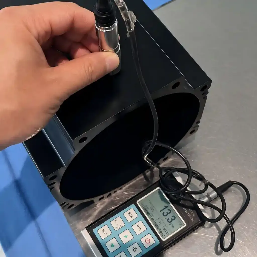
Outside color is not a direct measure of internal coverage, coating thickness or residual material. A thread gauge answers a fit question, while a visual examination answers an appearance question. Preserve those distinctions when preparing an inspection report.
A measurement method also needs suitable access and uncertainty. NIST's traceability guidance explains that traceability concerns measurement results and does not alone guarantee fitness for purpose. A calibrated instrument does not establish that its probe reached the relevant internal surface or measured the intended quantity.
Where internal coverage is critical, agree a representative verification method before production. The approach may need sacrificial samples, accessible witness geometry or another qualified technique, but the relationship to the actual cavity must be justified. A flat witness coupon does not automatically reproduce trapped gas or rinse exchange in a threaded blind hole.
Record inaccessible areas and the evidence supporting their acceptance. Avoid reporting complete inspection when the chosen method only covers the opening. If uncertainty remains material to product function, improve access or revise the verification plan before release.
Drawing and handoff details for the blind-hole finish
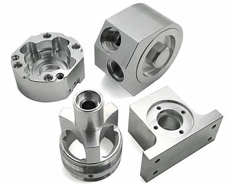
Mark internal coating requirements, masked zones, thread acceptance, allowed rack-contact regions and cosmetic boundaries. Supply sections showing the full cavity network, including intersections and terminations. These details let the finisher assess drainage and contact together.
For precision-machined features, state whether dimensions apply before or after finishing. If a feature is to be machined later, identify the exposed substrate and any resulting protection requirement. A later machining operation changes the finished surface condition and should not be an informal repair.
Keep the approved rack and masking concept with the process record where it affects acceptance. A new rack arrangement or substitute plug can change gas escape, drainage and contact marks even when the part drawing is unchanged.
Close release questions with evidence: required cavity treatment, final fit, absence of unacceptable residue and any delayed appearance condition. The goal is a finish route that the supplier can reproduce and the buyer can verify. A successful exterior sample is useful, but it is only one part of that agreement.
FAQ
Can a blind hole simply be left uncoated?
Yes, if the product design permits it and the exclusion is clearly specified. Review corrosion protection, electrical behavior, wear, cleanliness and the interface with adjacent treated surfaces before approving that choice. Define the masking boundary and any allowed transition at the opening. An uncoated cavity should be an intentional engineering condition with a verified process route, rather than an undocumented consequence of trapped gas or incomplete treatment discovered after production.
Does converting a blind hole to a through-hole always solve drainage?
It can improve access, but the complete orientation and connected geometry still matter. A through-hole may intersect a pocket that retains liquid or be blocked by a rack contact. It may also create an unacceptable leak path or weaken the component. Review the proposed change with both the product engineer and finisher. Approve the functional consequence first, then verify that the revised processing route actually improves gas escape and rinse exchange.
Should stained parts be stripped and anodized again?
That decision needs the responsible engineer and finisher to review the cause, alloy, coating requirement and dimensional margin. Stripping and reprocessing can change the base surface and final dimensions. Preserve the original defect evidence before selecting a remedy, and define the checks required afterward. A repeated finishing cycle is not automatically acceptable because it restores color. The finished part must still satisfy the complete product specification and any approved limits on rework.
Conclusion
Blind-hole finishing is controlled by the internal treatment requirement, the actual rack and masking arrangement, and a verification method that reaches the relevant question. Distinguish trapped gas from retained solution, and distinguish an acceptable outside surface from an acceptable hidden cavity. Release the finish route only when those conditions are resolved together.
Share the model and drawing with 6CProto for a quotation, including cavity sections, final thread requirements, masked surfaces and residue restrictions. These details allow the machining and finishing review to address the same accepted final state.
{“@context”: “https://schema.org”, “@type”: “FAQPage”, “mainEntity”: [{“@type”: “Question”, “name”: “Can a blind hole simply be left uncoated?”, “acceptedAnswer”: {“@type”: “Answer”, “text”: “Yes, if the product design permits it and the exclusion is clearly specified. Review corrosion protection, electrical behavior, wear, cleanliness and the interface with adjacent treated surfaces before approving that choice. Define the masking boundary and any allowed transition at the opening. An uncoated cavity should be an intentional engineering condition with a verified process route, rather than an undocumented consequence of trapped gas or incomplete treatment discovered after production.”}}, {“@type”: “Question”, “name”: “Does converting a blind hole to a through-hole always solve drainage?”, “acceptedAnswer”: {“@type”: “Answer”, “text”: “It can improve access, but the complete orientation and connected geometry still matter. A through-hole may intersect a pocket that retains liquid or be blocked by a rack contact. It may also create an unacceptable leak path or weaken the component. Review the proposed change with both the product engineer and finisher. Approve the functional consequence first, then verify that the revised processing route actually improves gas escape and rinse exchange.”}}, {“@type”: “Question”, “name”: “Should stained parts be stripped and anodized again?”, “acceptedAnswer”: {“@type”: “Answer”, “text”: “That decision needs the responsible engineer and finisher to review the cause, alloy, coating requirement and dimensional margin. Stripping and reprocessing can change the base surface and final dimensions. Preserve the original defect evidence before selecting a remedy, and define the checks required afterward. A repeated finishing cycle is not automatically acceptable because it restores color. The finished part must still satisfy the complete product specification and any approved limits on rework.”}}]}