
6CProto Engineering Guides
Gear, Thread & Fastener Feature Design
Engineering references for gear, thread & fastener feature design.
Updated November 2026 · 12 articles
Feature design is where machining cost hides
Most of a machined part is straightforward once the stock, the fixture and the tolerance are settled. The cost sits in a handful of features: a thread that needs a relief groove, a gear tooth that has to be cut rather than milled, a counterbore that lands on a curved surface. These articles exist because those features are where a drawing that looks complete turns into a conversation.
The common thread is access. A feature has to be reachable by a cutter, a tap, a hob or a wire, and the design either provides that access or pays for it in a second operation.
Threads: engagement, relief and runout
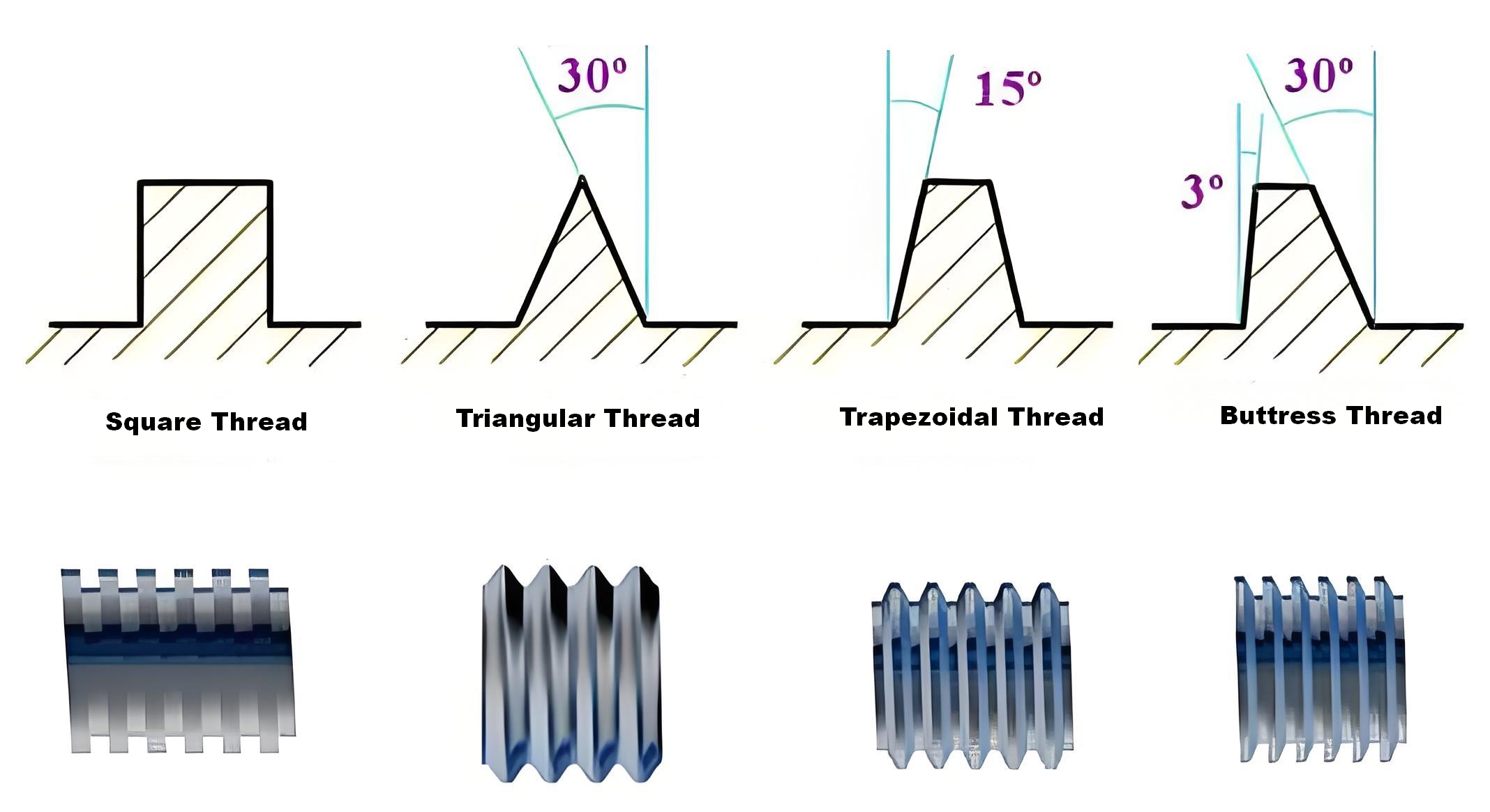
A thread needs enough engaged length to carry the load — around 1.5 times the nominal diameter in steel, twice in aluminium — and enough room at the end for the tap to finish. Without a relief groove or a drilled clearance, the last threads are partial, the fastener bottoms before the joint closes, and the assembly develops a gap that no torque value fixes.
The relief is also a machining feature: it gives the tool somewhere to stop, which is why it appears in drawings that have nothing to do with fasteners. A groove that is too narrow for the tool is worse than no groove.
Gears: module, backlash and method
Gear drawings fail in two ways. The tooth specification is ambiguous — module and diametral pitch are not interchangeable, and a pressure angle mismatch shows up as noise rather than as a dimensional error. Or the method is left open: hobbing, shaping, milling and wire EDM produce the same nominal tooth form with different accuracy, surface and cost.
Backlash is the other half. A gear pair specified with zero clearance binds when the centre distance tolerance lands on the wrong side, and a pair with generous backlash is noisy. Specifying the backlash range and the centre distance tolerance together is what makes the assembly buildable.
Fastener seating: counterbore, spotface, countersink
Three features, three jobs. A counterbore recesses a socket head so it sits below the surface. A spotface cleans a flat circular land on a rough or curved surface so the head seats squarely. A countersink accepts a flat-head screw and centres it. Using one where another belongs produces a head that stands proud, a joint that loosens, or a countersink cut into material too thin to hold it.
Each has a minimum material thickness and a tool access requirement, and each changes the inspection: a counterbore is checked for depth and diameter, a spotface for flatness and perpendicularity. Naming the feature correctly on the drawing is the cheapest way to get the right one.
When the feature needs a different process
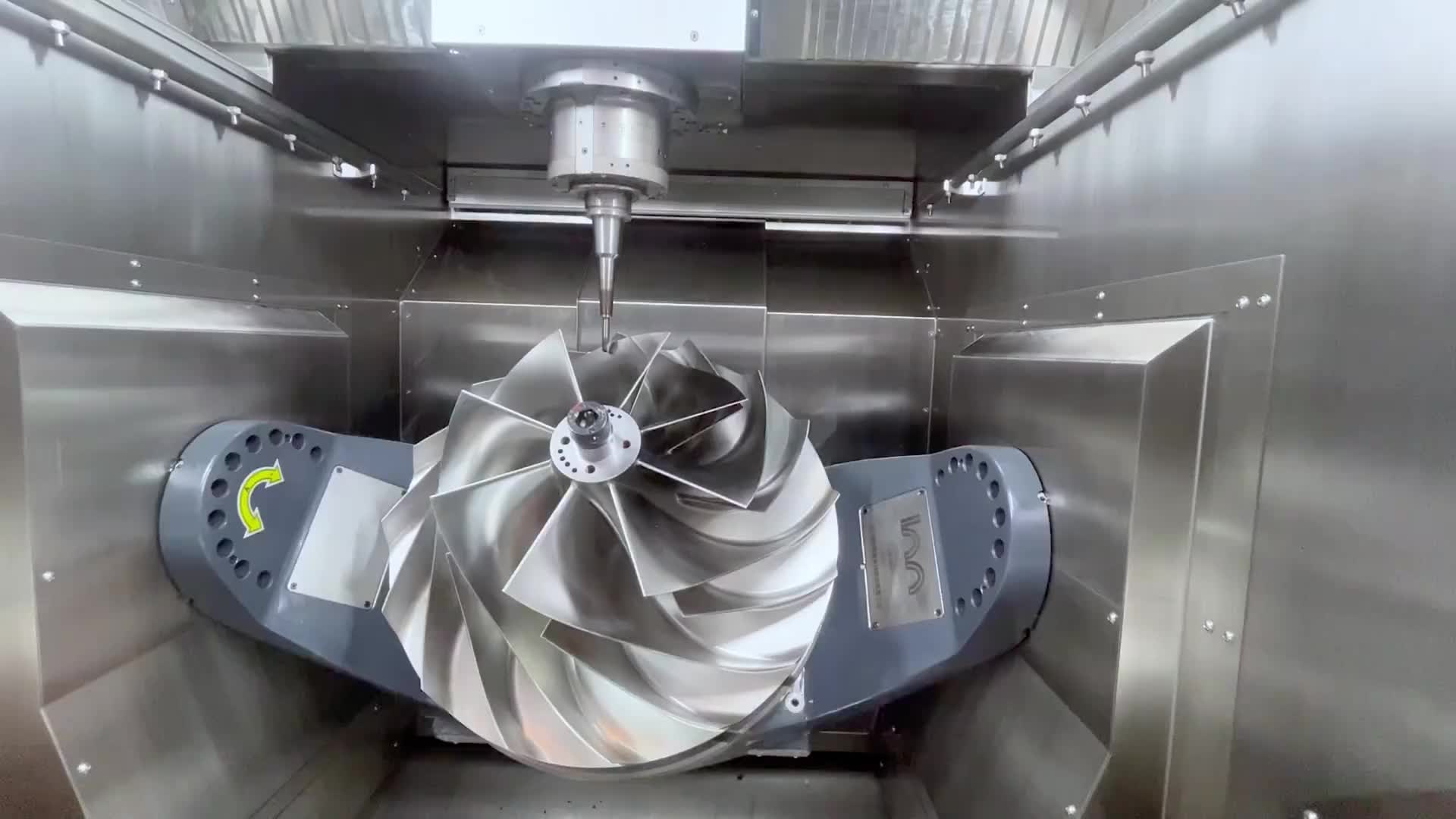
Some features cannot be produced by the process that makes the rest of the part, and the design has to decide whether to change the feature or add an operation. A sharp internal corner in a hardened block is a wire EDM feature and needs a start hole, which needs a location, which needs a drawing note. An internal spline or a gear tooth form may be cut by wire EDM, hobbed, or shaped, and each choice changes the achievable accuracy and the inspection method.
The cost of that decision is usually in the setup, not the cutting. A part that needs one wire operation, one mill setup and one inspection can be quoted confidently; the same part with three of each is a different project. Grouping features by the process that makes them — and by the face they are reached from — is what keeps a complex part buildable.
Find the guide for your next decision
Follow the guide that matches the feature, failure mode or project decision you are working on.
Wire EDM Start Hole Design: Threading Access, Location and Scrap Removal
Gear Module vs Diametral Pitch: Converting a Tooth Specification Correctly
Planetary Gear Carrier Design: Pin Bores, Alignment and Assembly Access
Thread Relief Groove Design: Tool Runout, Shoulder Clearance and Drawing Control
Gear Manufacturing Methods: Hobbing, Shaping, Milling and Wire EDM
Worm Gear Self Locking: When Backdriving Can Still Occur
Spotface vs Counterbore: Seating a Fastener Without Removing Excess Material
Bevel Gear vs Miter Gear: Ratio, Shaft Angle and Assembly Requirements
Spur Gear vs Helical Gear: Noise, Thrust Loads and Manufacturing Trade-offs
Gear Backlash: Specifying Clearance Without Creating a Binding Assembly
Gear Pressure Angle: Why a Matching Tooth Count Is Not Enough
Counterbore vs Countersink: Matching the Hole to the Fastener Head
Before you release the project
- Define the function, environment and the question this batch must answer.
- Specify material grade, geometry, quantity, finish and the dimensions that control fit.
- Agree the inspection method and the evidence required to accept the parts.
- Record the drawing revision and approval before production begins.
Common planning questions
Which CNC process should I consider first?
Start with the geometry. Rotational parts are usually candidates for turning; pockets and planar faces suggest milling. Tool access, setups and hardened features decide whether multi-axis machining or EDM adds value.
Should every dimension have a tight tolerance?
Specify tight limits only where fit or function requires them, and define how those features will be measured. Broad tight-tolerance notes can add cost without improving the part.
What should accompany the CAD model?
Provide a controlled drawing, material grade, quantity, critical dimensions, finish and inspection requirements. Identify cosmetic and sealing surfaces before the quote.
Move from guidance to a reviewed project
Send the CAD model and drawing with material, quantity, finish and inspection requirements. Use the relevant service page to review the available manufacturing route.