

Explore Gear, Thread & Fastener Feature Design
A fastener can sit squarely on a small machined pad without being hidden below the surrounding surface. That distinction is central to spotface vs counterbore selection. A spotface establishes a local bearing surface, while a counterbore generally provides a cylindrical recess for the fastener head or another component. The exact depth, diameter and seating requirements still belong on the drawing.
Removing more material than the joint needs can weaken a thin boss, break into a passage or make inspection harder. Removing too little can leave a washer supported on an uneven surface or prevent a head from clearing its surroundings. This guide connects the seating function with the section geometry, tool approach and measurements needed to accept the finished feature.
Which function decides spotface vs counterbore?
Decide whether the joint needs a seat or a recess.
A spotface creates a local bearing pad, while a counterbore recesses a component; specify the required seating geometry rather than relying on the feature name alone.
A spotface is particularly useful where a casting, curved surface or irregular stock face cannot provide the intended fastener support. It need not conceal the head. A counterbore usually has a controlled cylindrical diameter and depth so the head, washer or inserted component fits within an envelope. Both can have a flat bottom, so bottom shape alone is not a sufficient distinction.
Use the selected fastener manufacturer’s dimensions to define the head and washer envelope. Carr Lane’s counterbore data is a useful example of component specific hole information, not a replacement for the actual fastener specification. Check the bearing area and adjacent features before deciding that a deeper recess improves the joint.
Identify whether the washer is required or optional in the assembly. Its presence changes the bearing envelope and head stack, so the seat cannot be finalized independently of it.
Depth and remaining wall thickness
The useful section is the material remaining below and around the machined seat. A deeper feature may improve head clearance while reducing the ligament above an internal passage or between adjacent holes. Evaluate that tradeoff with the joint’s loading and the true stock condition.
Do not measure remaining wall only from nominal outside dimensions if the opposite surface is cast, formed or otherwise variable. Establish the minimum available section from the relevant tolerances and manufacturing condition. A spotface specified as minimum cleanup can remove different amounts at different locations; a counterbore with a fixed depth can intersect a variable wall differently across parts.
The drawing should therefore connect seat depth to the datum that controls its function. If the seat carries a washer, check full support without encroaching on a fillet or neighboring opening. If the head must remain below a cover, check the assembled maximum height as well. A generic shallow recess is not an engineering acceptance criterion for either condition.
A depth change can also alter the effective fastener engagement and available thread length. Review the complete joint section rather than only the material directly below the seat.
Tool access and concentricity
The cutter needs room for its diameter, body, holder and approach. A spotface on the far side of a hole may require a back spotfacing tool or a different setup; it is not necessarily reachable with a standard cutter from the visible face. Include the pilot and retract envelope when evaluating an inaccessible feature.
Concentricity language should be used carefully. The functional requirement may be adequate clearance around a bolt and sufficient bearing support, or it may require a controlled relationship between a locating bore and a seat. Define that relationship through the appropriate drawing controls rather than adding an undefined “concentric” note. The ASME dimensioning and tolerancing framework provides the context for an agreed drawing language.
For a milled mounting seat, review how the tool is located relative to the hole and datum surfaces. A pilot may guide some tools, but it does not remove the need to verify the completed relationship or account for a distorted or oversized pilot hole.
Keep tool guidance and feature location distinct in the inspection plan. A pilot guided operation can still follow an incorrectly positioned hole or an unsuitable datum relationship in production.
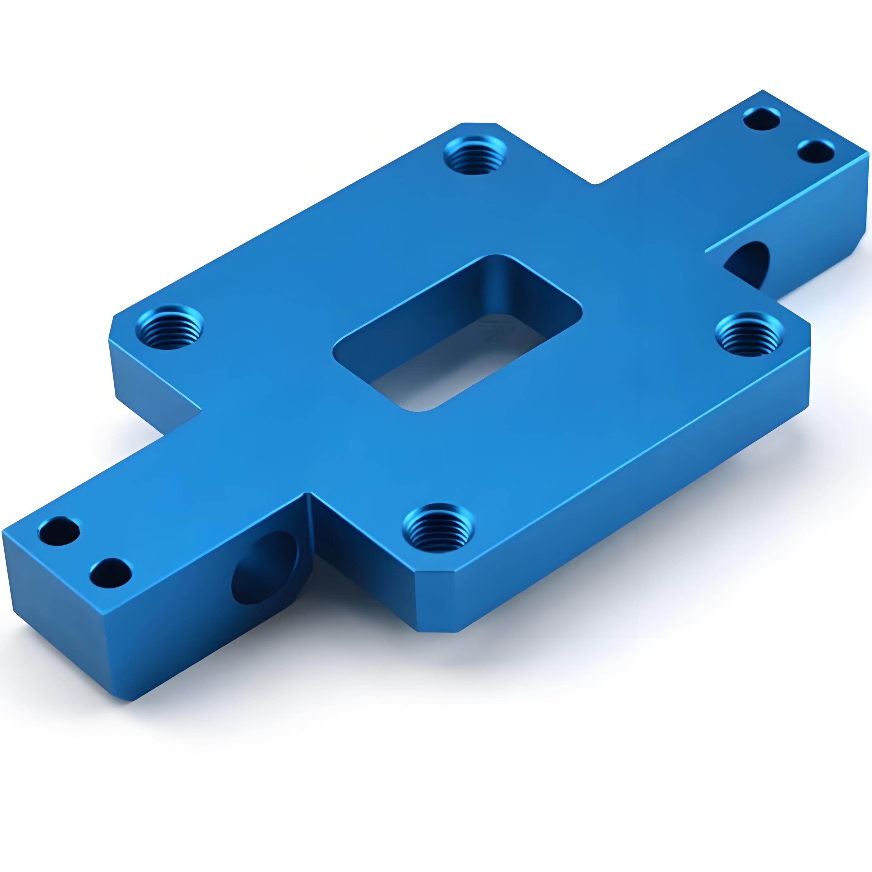
Calling out the feature on a drawing
Name the bearing diameter, seating plane and required cleanup condition explicitly. For a counterbore, define depth and the clearance diameter needed for the actual head or inserted component. For a spotface, state whether the requirement is a fixed geometry or sufficient cleanup within a maximum permitted material removal.
Drawing symbols are useful only when interpreted under an identified convention. Do not assume that the same abbreviated note or CAD hole feature conveys every inspection requirement to every supplier. Add a section view when the seat lies on a curved face, near a passage or behind another feature. Confirm that the drawing and the solid model express the same end condition.
If a chamfer or edge break surrounds the recess, ensure it does not consume the required washer bearing land. Sandvik’s chamfer milling guidance illustrates that an edge operation has its own tool and access considerations. Separate necessary burr removal from a large cosmetic chamfer, especially where the remaining bearing area is limited.
If a drawing uses a minimum cleanup note, define the maximum removal and full bearing area. Otherwise, two inspectors can accept different end conditions from the same wording.
Dimensioned section showing access and remaining material
Consider a hypothetical boss with 10 mm total nominal thickness and an underlying passage whose upper boundary is 6 mm below the top datum. Assume the design permits a 1 mm spotface cleanup but a proposed counterbore would be 4 mm deep. Before tolerances, the nominal ligament above the passage is 5 mm after the spotface and 2 mm after the counterbore.
Those values come from 6 – 1 and 6 – 4 respectively. They do not establish a safe minimum section: the example omits pressure, load, stress concentration and manufacturing variation. Its purpose is to expose a consequence that is invisible in a top view.
Add the maximum seat depth and the least favorable passage position to the real drawing review. Also include head height and washer thickness in the assembled clearance check. A shallow seat may meet the bearing requirement while a separate cover recess solves the packaging problem. Resolve that design choice before machining, rather than accepting the deepest feature that happens to clear the fastener.
Check whether the nominal section remains accessible for measurement after assembly. If not, define the necessary in-process evidence before the cover or adjoining component blocks the feature.
Process and inspection method comparison table
Select measurements that establish the seating function and remaining envelope. A depth reading is useful, but it cannot show that the bottom provides continuous support or that a sloped adjacent surface has been fully cleared. Inspect the relationship required by the assembly rather than only the easiest accessible dimension.
| Requirement | Possible verification | Limit to address |
|---|---|---|
| Seat diameter and access | Appropriate dimensional measurement | Edge chamfer must not be counted as bearing land |
| Depth or cleanup | Referenced depth or profile measurement | Datum and rough surface variation matter |
| Seating plane | Plane or profile evaluation | One depth point cannot establish full support |
| Head clearance | Approved assembly or envelope check | Include washer and tolerance stack |
The Mitutoyo surface measurement guide also distinguishes surface texture evaluation from dimensional form. If texture controls sealing or bearing behavior, define its method separately. Coordinate the measurement plan with the specified tolerances before choosing an inspection tool.
Where the seat is interrupted by a hole or slot, identify the permitted support area. A diameter measurement alone cannot establish how much continuous bearing material remains locally.
Acceptance checks on the functional feature
Acceptance should reproduce the functional references of the joint. Verify the hole, seating surface and surrounding envelope in the condition specified for assembly. If a coating is applied later, identify whether dimensions and clearances apply before or after that operation.
A representative fastener can help reveal interference, but a successful hand fit is not proof of preload capability or adequate bearing stress. Similarly, a bolt head that sits below the outside surface may still contact a radius at the bottom corner. Inspect the specified seating land and corner relief, not only the top clearance.
For a turned component, the seat may be produced on a different axis or setup from the main bore. Review turned datum features when planning that transfer. Sandvik’s shoulder milling guidance is relevant where a cutter must produce the recess wall and floor together. Distinguish a tool’s nominal geometry from the measured feature, particularly when an internal corner radius affects the head or washer.
A coating can change head clearance and bearing contact. State the inspection stage and evaluate the final assembled condition rather than accepting only an uncoated machining sample alone.

Drawing callouts to resolve before quoting
Before quoting, resolve the actual fastener part number, head envelope, washer use and tightening access. State whether the function is bearing support, packaging clearance, alignment or a combination. A feature serving several functions needs acceptance criteria for each rather than one ambiguous nominal depth.
Provide a section showing the minimum remaining wall, nearby passages and the datum used for the seat. If cleanup is permitted to vary, define its maximum extent and the area that must be fully machined. State the permitted bottom corner and edge break so that a supplier does not remove additional support to achieve an unspecified visual finish.
The model should also show obstructions that affect tool access. Haas’s mill programming documentation illustrates why motion and offset review belongs to a defined machine setup; it cannot establish reach from a drawing alone. Agree whether an alternate approach or setup changes the drawing datums, and require approval before a seat is relocated to make it easier to machine.
Ask whether a tool radius is allowed at the recess bottom. Leaving this unresolved can cause a head to bottom on a corner before its bearing face contacts the seat.
FAQ
What does a counterbore symbol look like?
The commonly used counterbore symbol resembles a squared U, followed by diameter and depth information according to the drawing convention in use. The symbol alone does not define every detail of a functional seat. Read the complete note, referenced standard and section view, including any quantity, edge condition or relationship to another hole. If a model generated callout is ambiguous, resolve it with the drawing owner before manufacturing rather than interpreting the icon in isolation.
Can a counterbore be made with an end mill?
An end mill can produce some counterbores through an appropriate pocketing or interpolation operation, provided tool geometry, access, rigidity and the required bottom condition are suitable. Other features may favor a dedicated counterboring or spotfacing tool. Choose the route from the finished geometry and inspection requirements, not from the feature name alone. Review the internal corner radius and depth approach, since a tool that reaches the feature may still leave an unsuitable seating condition.
Does a spotface need to be completely bright after machining?
That depends on the specified bearing area and cleanup requirement. A defined pad may need full cleanup within its functional seat, while adjacent nonbearing material can remain as formed or cast if the drawing permits it. Appearance alone is not a reliable acceptance rule. Define the required machined area, maximum material removal and surface condition so that an operator does not keep cutting simply to remove every visual trace from an irregular surrounding surface.
Conclusion
Choose a spotface when the joint needs a controlled local seat, and a counterbore when the assembly also requires a defined recess. Then verify the choice against the remaining section, fastener envelope and tool access. The feature name is the start of the specification, not the complete acceptance requirement.
A section view often resolves more risk than a deeper nominal callout. Show the bearing land, bottom corner, nearby passage and functional datum; distinguish head clearance from mechanical joint validation. This lets manufacturing and inspection work toward the same result without removing unnecessary material. For a component review, send the drawing, selected fastener and relevant assembly section for quotation. Include the required cleanup and remaining wall limits so that process choices can be assessed against the actual joint.
{“@context”: “https://schema.org”, “@type”: “FAQPage”, “mainEntity”: [{“@type”: “Question”, “name”: “What does a counterbore symbol look like?”, “acceptedAnswer”: {“@type”: “Answer”, “text”: “The commonly used counterbore symbol resembles a squared U, followed by diameter and depth information according to the drawing convention in use. The symbol alone does not define every detail of a functional seat. Read the complete note, referenced standard and section view, including any quantity, edge condition or relationship to another hole. If a model generated callout is ambiguous, resolve it with the drawing owner before manufacturing rather than interpreting the icon in isolation.”}}, {“@type”: “Question”, “name”: “Can a counterbore be made with an end mill?”, “acceptedAnswer”: {“@type”: “Answer”, “text”: “An end mill can produce some counterbores through an appropriate pocketing or interpolation operation, provided tool geometry, access, rigidity and the required bottom condition are suitable. Other features may favor a dedicated counterboring or spotfacing tool. Choose the route from the finished geometry and inspection requirements, not from the feature name alone. Review the internal corner radius and depth approach, since a tool that reaches the feature may still leave an unsuitable seating condition.”}}, {“@type”: “Question”, “name”: “Does a spotface need to be completely bright after machining?”, “acceptedAnswer”: {“@type”: “Answer”, “text”: “That depends on the specified bearing area and cleanup requirement. A defined pad may need full cleanup within its functional seat, while adjacent nonbearing material can remain as formed or cast if the drawing permits it. Appearance alone is not a reliable acceptance rule. Define the required machined area, maximum material removal and surface condition so that an operator does not keep cutting simply to remove every visual trace from an irregular surrounding surface.”}}]}