

A manifold can pass an outside dimensional inspection while a burr remains at the intersection of two internal holes. Cross hole deburring addresses those hidden edges, where drilling can leave attached material that obstructs flow, detaches later or damages a downstream component. The challenge is to remove the unwanted material without rounding a metering edge or changing the passage more than the design permits.
The process needs a sectioned view of the intersection and a defined acceptance condition. “Deburr all edges” is rarely enough for an inaccessible fluid passage. This guide follows the geometry from burr formation through method selection, internal verification and cleaning, with particular attention to the difference between a removed burr and an acceptably preserved functional edge.
Where does cross hole deburring need special attention?
Examine the complete internal intersection.
Intersecting drilled passages can leave irregular internal burrs whose shape depends on geometry and machining order; access and acceptance must cover the hidden edge around the full intersection.
The breakthrough region can differ around its circumference because the tool meets a curved or angled surface. A burr at the near side may be visible through the opening while another remains behind the intersection. Drill sequence, material condition, tool wear and support influence the starting condition.
HEULE’s cross bore deburring guidance illustrates specialized access to such geometry. Before choosing a tool, show both hole diameters, angle, offset and available entry length. Distinguish a centered perpendicular intersection from an offset or angled one. A process qualified on one geometry should not be assumed to reach every edge of another simply because the nominal hole diameter matches.
Map each intersection separately when a manifold contains several passages. A common drill size does not establish identical access where depth, angle or neighboring protected features change along the component.
Access for mechanical and thermal methods
Mechanical tools need a path to the burr and space for the cutting or compliant element to operate. Check the smallest access diameter, intersection shape, stroke and retract conditions. A tool that enters the bore can still fail to contact the full target edge or can damage the opposite wall.
HEULE’s COFA tool information is an example of a purpose designed deburring approach, not a universal recommendation for every cross hole. Other routes include controlled abrasive processes, electrochemical deburring and thermal methods, each with distinct geometry and material constraints. Extrude Hone describes electrochemical deburring as controlled anodic removal and thermal deburring as a separate process family.
Review what each method can remove, what surfaces it may affect and what cleaning follows. Do not imply these specialist processes are available or approved merely because a component is machinable. For an RFQ, identify the required result and ask the proposed route to demonstrate reach, edge preservation and postprocess cleanliness on representative geometry.
Include the removal of process residues in the route comparison. A method that removes a burr can still leave contamination that requires a defined subsequent cleaning and verification operation afterward.
Protecting sealing and metering edges
A sealing land, valve seat or metering edge may need a controlled sharpness or small edge condition rather than general smoothing. Removing the burr is necessary, but removing more material can change leakage, flow or assembly behavior. Mark these surfaces as protected or explicitly define the permitted change.
Separate functional edges from noncritical passage intersections. A broad instruction to break all internal edges can conflict with a drawing requirement that controls a flow area. For a metering feature, the relevant acceptance may include geometry and a functional flow test; neither should be inferred from a visually smooth appearance.
Coordinate the initial hole making sequence through the milling process review. Reducing the initial burr can make the finishing problem easier, but it does not prove complete removal. Sandvik’s machining troubleshooting guidance is useful for reviewing tool and process condition. Keep any resulting edge change inside the drawing limits rather than compensating for a large burr with uncontrolled additional finishing.
If a functional edge needs a small controlled radius, specify it directly. A general burr free statement does not establish the size or uniformity of an intentionally rounded metering edge.
Inspection of inaccessible intersections
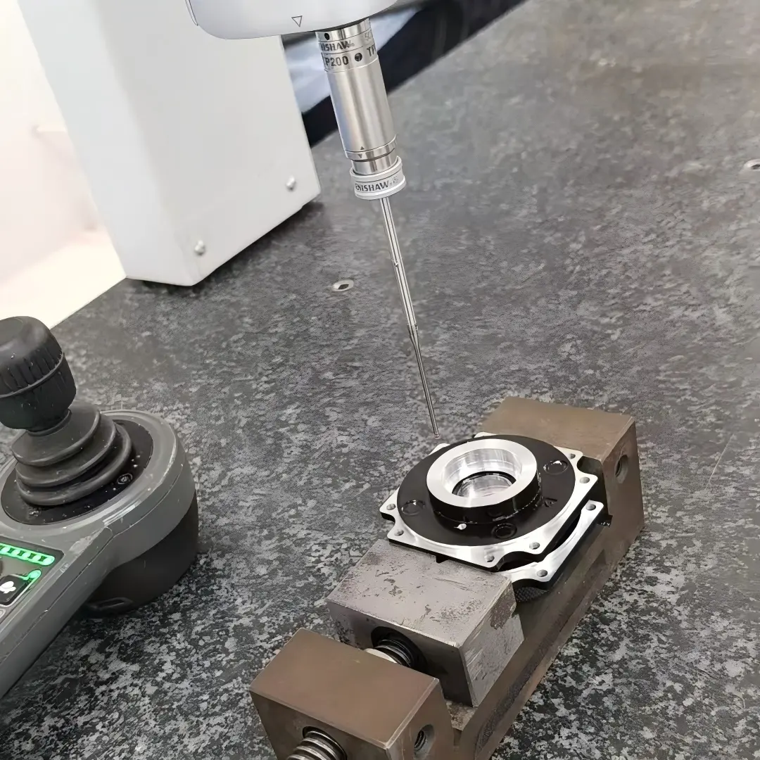
Internal inspection needs sufficient access, lighting and resolution to answer the actual acceptance question. A borescope can reveal many internal conditions, but its view may not cover the full circumference or distinguish a small attached burr from a shadow without a defined procedure.
Map the required viewing directions and retain representative images with part orientation. If the edge is inaccessible, qualification may need a sectioned sample, replica or another appropriate method. A clean outlet or successful air blow does not establish that all attached burrs are gone. Likewise, a particle test evaluates released contamination under its procedure, not every attached internal feature.
Define these limitations within the inspection requirements. Where dimensional change matters, select a method able to measure that change or validate a representative destructive examination. The Mitutoyo texture measurement guide reinforces that a surface parameter is method dependent; an accessible roughness reading should not be repurposed as proof of burr removal deep inside a passage.
Retain images with a recognizable reference and scale where practical. An isolated close view without orientation can be difficult to associate with the intended intersection during later quality review work.
Dimensioned section showing access and remaining material
Assume a hypothetical 6 mm transverse bore intersects a 10 mm main passage at 90 degrees. A metering land begins 2 mm from the intersection, and its edge condition must remain unchanged. These dimensions describe the review example only and do not define an acceptable burr size or a preferred tool.
The section view should show the full deburring envelope, including any cutter projection or flow path used by the finishing method. If the tool needs 3 mm of working clearance beyond the edge, the 2 mm separation exposes a potential conflict. Resolve it through a different tool, sequence or design review rather than assuming the finishing action stops exactly at the burr.
Include hole position and diameter tolerances when checking the least favorable access condition. An offset intersection can reduce reach on one side while increasing it on the other. For a component with turned sealing features, show how the turning and drilling datums relate so that the protected land is located consistently across the manufacturing sequence.
Review whether plugging or assembly changes the cleaning path. The process must remove debris before closure and prevent new contamination from being introduced by the subsequent operation itself afterward.
Process and inspection method comparison table
Compare methods against the same drawing requirement and sample geometry. The table gives selection questions rather than a claim that one route always produces the cleanest or most precise result. The process provider should explain its proposed control and inspection boundary.
| Method family | Access concern | Acceptance concern |
|---|---|---|
| Mechanical deburring | Tool reach and full edge contact | Residual burr, tool marks and edge size |
| Abrasive finishing | Media access and flow distribution | Protected surfaces and material removal |
| Electrochemical deburring | Tooling and electrolyte access | Localized removal and cleaning requirements |
| Thermal deburring | Process compatibility with geometry and material | Residues, affected surfaces and subsequent cleaning |
The ASME dimensioning framework supports a clear geometric specification, but a generic drawing convention does not establish a process qualification. Keep functional edge limits, cleanliness and dimensional results as separate acceptance items. Where a supplier proposes an alternate method, compare its evidence on the actual critical features rather than treating all burr removal routes as automatically equivalent.
Where a method affects several passages at once, identify which features receive the strongest and weakest action. Uniform external appearance does not establish uniform internal material removal across the geometry.
Acceptance checks on the functional feature
Validate the process using representative starting burrs and the relevant extremes of geometry. A sample drilled with a new tool under favorable conditions may not represent the production burr after the agreed tool life. Identify the initial condition and do not allow the qualification sample to be hand cleaned before the finishing trial.
After processing, inspect for remaining attached material, excessive rounding and damage to protected surfaces. Then clean and assess contamination under the specified procedure. If flow or leakage is critical, perform the appropriate functional check in addition to visual and dimensional evaluation.
Document the sampling basis and inspection coverage. A sectioned trial part can reveal whether the selected method reaches a hidden edge, but it does not establish ongoing control by itself. Define how tool condition, process settings and cleaning will be maintained. When an inspection cannot directly observe every production intersection, the qualified process and its monitoring become especially important; state that boundary rather than claiming universal visual confirmation from a limited view.
A production monitoring plan should identify the signals that trigger investigation. Tool wear or a changed initial burr can reduce the validity of a previously successful deburring qualification over time.
Drawing callouts to resolve before quoting
Provide an intersection map with hole sizes, angles, offsets, depths and the sequence where relevant. Mark sealing lands, metering edges and surfaces that must not be rounded or polished. Define the permitted edge condition and the cleanliness requirement separately from a general external deburring note.
State how the result will be accepted, including internal viewing access, representative destructive examination or functional testing when required. If a plug later closes the passage, schedule the internal check and cleaning before closure, then define any final verification needed after assembly. Otherwise the sequence can make the agreed inspection physically impossible.
Ask the supplier to identify the proposed method and any specialist processing rather than assuming a particular route from the finished appearance. Record approval requirements for changes to drilling order, finishing tool or process. The final manufacturing record should connect the starting geometry, deburring and cleaning evidence to the same drawing revision, allowing a later flow or contamination issue to be investigated without reconstructing undocumented choices.
Coordinate the drawing note with any downstream cleanliness specification. Conflicting instructions can leave manufacturing unsure whether an edge is accepted by visual inspection, a particle test or both methods together.
FAQ
Does flushing remove an attached internal burr?
Flushing can remove loose material under defined conditions, but it should not be assumed to detach every attached burr. A remaining burr may survive cleaning and break free later in service. Specify burr removal and cleanliness as separate requirements, then verify each using an appropriate method. The process should also avoid creating new loose fragments or leaving finishing media in the passage. A clean fluid sample is useful evidence only within the scope of its test procedure.
Can a borescope prove that an intersection is burr free?
It can provide valuable evidence when the required edge is visible with adequate lighting and resolution, but coverage and detection capability must be established. Hidden portions, shadows and viewing angle can limit the result. Define orientations and acceptance examples, and use representative sections or another suitable method when the internal geometry cannot be judged reliably. Record what was actually observed rather than using a general borescope check note as proof of every inaccessible surface.
Should every internal edge be rounded after drilling?
No. Some internal edges control metering, sealing or flow behavior and may need a specific condition. General rounding can change those functions. Identify protected edges and define permitted material removal on the drawing, while giving noncritical intersections their own burr removal requirements. If a process affects both regions, validate its selectivity and inspect the functional feature afterward. Removing an unwanted burr and intentionally creating a radius are different manufacturing objectives that should not be combined without review.
Conclusion
Plan internal deburring from a complete view of the intersection, including protected surfaces and the least favorable tool access. Select the method by what it can reach and preserve, then validate the result on representative starting burrs and geometry. Keep attached burr removal, edge size and cleanliness as separate requirements.
Inspection coverage must be as explicit as the process route, particularly before a plug or assembly makes the passage inaccessible. A sectioned trial, controlled internal images and a relevant functional test can provide complementary evidence, each within its limits. For a component review, send the passage sections, protected edge requirements and inspection expectations for quotation. A defined internal acceptance target is more useful than an unrestricted instruction to deburr every edge.
{“@context”: “https://schema.org”, “@type”: “FAQPage”, “mainEntity”: [{“@type”: “Question”, “name”: “Does flushing remove an attached internal burr?”, “acceptedAnswer”: {“@type”: “Answer”, “text”: “Flushing can remove loose material under defined conditions, but it should not be assumed to detach every attached burr. A remaining burr may survive cleaning and break free later in service. Specify burr removal and cleanliness as separate requirements, then verify each using an appropriate method. The process should also avoid creating new loose fragments or leaving finishing media in the passage. A clean fluid sample is useful evidence only within the scope of its test procedure.”}}, {“@type”: “Question”, “name”: “Can a borescope prove that an intersection is burr free?”, “acceptedAnswer”: {“@type”: “Answer”, “text”: “It can provide valuable evidence when the required edge is visible with adequate lighting and resolution, but coverage and detection capability must be established. Hidden portions, shadows and viewing angle can limit the result. Define orientations and acceptance examples, and use representative sections or another suitable method when the internal geometry cannot be judged reliably. Record what was actually observed rather than using a general borescope check note as proof of every inaccessible surface.”}}, {“@type”: “Question”, “name”: “Should every internal edge be rounded after drilling?”, “acceptedAnswer”: {“@type”: “Answer”, “text”: “No. Some internal edges control metering, sealing or flow behavior and may need a specific condition. General rounding can change those functions. Identify protected edges and define permitted material removal on the drawing, while giving noncritical intersections their own burr removal requirements. If a process affects both regions, validate its selectivity and inspect the functional feature afterward. Removing an unwanted burr and intentionally creating a radius are different manufacturing objectives that should not be combined without review.”}}]}