

Explore Gear, Thread & Fastener Feature Design
A recessed fastener can look flush in CAD yet stand proud on the first assembly. The recess may match the head diameter but not its underside, or the drawing may control hole depth without controlling the surface that actually supports the screw. Either mistake can leave the head tilted, reduce the remaining wall or change how the joint clamps.
The counterbore vs countersink decision starts with the selected fastener. A counterbore provides a cylindrical recess with a supporting shoulder; a countersink provides a conical seat for the corresponding head geometry. Choose the feature from the controlled fastener definition and the joint section, then establish the required protrusion, bearing engagement and inspection method.
This comparison addresses that local hole feature. General fastener preload design, thread engagement and overall joint capacity remain separate engineering tasks. A recess that accepts the head is necessary, but it does not by itself validate the complete bolted assembly.
Which counterbore vs countersink geometry supports the head?
The recess must match the fastener’s bearing geometry.
Use a flat supporting shoulder for a compatible cylindrical head and a matching conical seat for a countersunk head; verify the actual fastener standard before defining dimensions.
The visible outline of the head is not enough. Check the underside, underhead transition, bearing diameter and any washer or captive component that remains in the assembly. A counterbore that clears the head can still interfere with its underhead radius. A conical seat with the wrong included angle can concentrate contact instead of supporting the intended bearing surface.
The NASA Fastener Design Manual treats head and joint choices as part of a larger fastening design problem. Use the selected product drawing for its actual dimensions rather than substituting a nominal size from memory. When the fastener is already specified, the recess should be coordinated with it. If the designer changes the head style to reduce the package height, revisit the local wall and seating geometry instead of retaining the earlier hole definition.
Thin wall and edge-distance limits
Removing material for a recess changes the local section that carries the clamping load. A deeper counterbore reduces the floor beneath its shoulder; a larger countersink moves the conical intersection outward and can approach an edge or adjacent hole. These effects belong in a section view with the relevant tolerances.
Start with the finished part thickness, not the raw stock dimension. Include nearby pockets, backside chamfers and any later machining that removes supporting material. For sheet or a thin flange, a through condition can occur before the desired head seating is achieved. That conflict may require a different fastener arrangement rather than a deeper cut.
The Carr Lane counterbore data illustrates why recess dimensions are associated with a particular application and hardware arrangement. It is not a universal minimum-wall rule for every joint. Identify the remaining section the design requires, then check the selected head and recess against it. Where the joint carries a critical load, the responsible designer must evaluate the local material and bearing condition, including the worst permitted geometry.
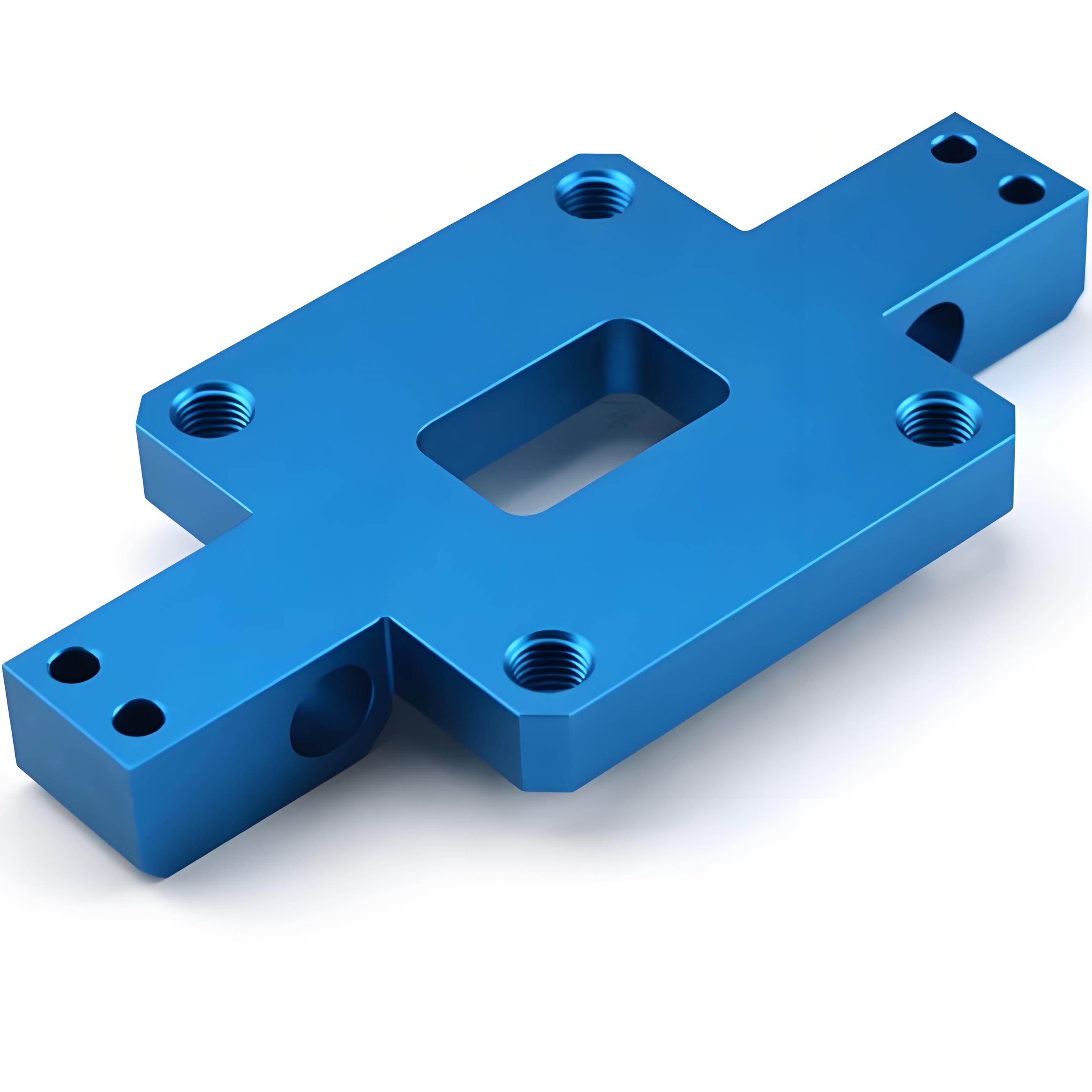
Depth and diameter control
A recess depth must be measured from a defined surface to the feature that controls seating. If the drawing instead dimensions a convenient tool tip location, different cutter geometries can produce different functional results. Separate the supporting shoulder or cone from nonfunctional drill-point or tool-clearance details.
For a counterbore, diameter and depth establish different clearances. The diameter must accommodate the head and installation tool as required; depth influences protrusion and the remaining floor. For a countersink, diameter, angle and axial depth are linked, so avoid inconsistent dimensions that force the supplier to choose which one governs.
The Autodesk chamfer-geometry documentation distinguishes the dimensions used to define a bevel. Apply the same discipline to a conical recess: state the intended geometry rather than assume a default angle. In a milling review, clarify whether the operation needs a controlled seating surface, a clearance relief or both. Those outcomes can require different process and inspection attention even when one tool makes them.
Where the screw must be tightened after installation, check driver access and engagement as well as head clearance. A head that enters the recess may still leave insufficient room for the specified assembly tool.
Inspecting seating and protrusion
Seating acceptance needs a reference condition. A loose screw dropped into a recess is not the same observation as an assembled fastener under the specified installation procedure. Define which condition the protrusion requirement addresses and which head or mating hardware is used for an assembly check.
Inspect the recess itself before relying on that functional trial. Diameter, supporting depth, cone geometry and relation to the through hole may need separate checks. Burrs or debris can hold the head away from the intended surface, while a tilted seat may produce apparently acceptable protrusion at only one location.
The standards and tolerances information can support the measurement discussion, but the actual acceptance rule must identify the controlled surfaces and limits. Where appearance matters, distinguish the cosmetic requirement from the load-bearing seat. One can pass while the other fails. A first-article record should therefore connect the measured recess to the selected fastener and assembly condition rather than simply state that the screw fits.
Recess section and remaining-material example
Consider an explicitly assumed 8.0 mm thick flange with a 3.0 mm deep counterbore measured from the finished top face. If no other feature removes material beneath that shoulder, the nominal floor is 8.0 – 3.0 = 5.0 mm. This arithmetic describes the section; it does not establish an allowable bearing load or a minimum safe thickness.
The drawing review must then consider the dimensional limits and the actual through-hole and underside features. A backside pocket that overlaps the recess can reduce the remaining section beyond the simple calculation. The section should show that intersection rather than leave it hidden in separate views.
For a countersink alternative, do not transfer the 3.0 mm depth automatically. Establish the cone from the specified head geometry and evaluate the resulting local thickness. Comparing the two options requires the same protrusion and support objectives. Otherwise a shallower-looking feature can appear preferable only because it has not been required to achieve the same assembly result.
Manufacturing and inspection comparison
Both feature types can be produced in a machining sequence, but their acceptance challenges differ. The appropriate method depends on access, tool geometry and the surfaces used to establish the hole’s location. A nominally simple recess may become difficult to inspect when a deep pocket blocks the measuring probe.
The table separates these questions. It does not assign a general accuracy advantage to one recess type or one instrument.
| Requirement | Counterbore | Countersink | Acceptance evidence |
|---|---|---|---|
| Head support | Defined shoulder or bearing face | Defined conical contact | Geometry matched to selected fastener |
| Protrusion | Depends on shoulder depth and head height | Depends on cone and head geometry | Measurement in the specified assembly state |
| Remaining section | Floor beneath the shoulder | Section around the tapered opening | Dimensioned section at limiting geometry |
| Tool access | Clearance for the recess cutter | Approach for the angled cutting edge | Approved manufacturing sequence |
The ASME Y14.5 standard overview establishes the role of controlled drawing language. Use the specified drawing standard to communicate geometry; hardware dimensions and attainable process limits still require their own technical review.
Include the permitted head variation in this comparison. A single nominal CAD representation of the screw does not establish the most demanding protrusion or clearance condition.
Functional acceptance at the hole
The meaningful result is a controlled relationship between the recess, through hole and surrounding part. If their axes or locating references disagree, the fastener can contact an unintended surface even when the individual diameters are within limits. Identify the datum relationship needed for the actual assembly.
Review the inspection sequence before finishing or assembly hides the seat. A measurement method should demonstrate the required characteristic without damaging the bearing surface. If access makes a direct reading impractical, agree on suitable alternative evidence before production rather than treating the absence of a reading as acceptance.
Manufacturing verification also needs the correct program and setup. The Haas mill programming manual illustrates the importance of coordinates, offsets and controlled program interpretation on that controller family. It is a machine-specific reference, not a universal recess program. For the purchased component, connect the dimensional report to the released drawing revision and the final operation that can change the seat. That preserves the meaning of acceptance after rework or a process change.

Drawing callouts to resolve before quotation
A complete quotation package identifies the fastener specification, recess dimensions, supporting geometry and permitted protrusion. Include a section where remaining wall or nearby features constrain the design. Do not rely on the model alone to communicate whether flush appearance or a controlled load-bearing seat is the primary requirement.
Separate a required recess from a general deburring instruction. The latter may address incidental sharp edges but should not authorize a supplier to modify the supporting cone or shoulder. If a washer, coating or captive element changes the installed stack, include it in the assembly definition rather than expecting it to be inferred.
For custom machined components, identify which dimensions are fixed by mating hardware and which may be reviewed for manufacturability. A proposed change should be assessed against the same fastener and remaining-section requirements as the original design. Record accepted changes in the controlled drawing so future orders do not depend on a quotation note that describes a different recess from the released part.
FAQ
How should a counterbore be called out on a drawing?
Identify the through-hole requirement and the counterbore diameter and supporting depth, with the relevant datum or surface reference. Add the required positional or geometric controls where the assembly depends on them. The selected drawing standard determines the notation, so avoid mixing symbols or conventions without explanation. A modelled recess does not remove the need to identify which dimensions and surfaces govern acceptance, particularly when a hole is repeated across a patterned mounting interface.
Does a countersink always need a particular standard angle?
The angle must match the specified head and the intended seating arrangement. Different fastener systems can use different head geometry, so a familiar default is insufficient. Verify the actual fastener definition and dimension the recess accordingly. If a supplier proposes a readily available cutter with a different angle, assess the resulting contact and protrusion before accepting it. A head that sits below the outer face may still be supported incorrectly.
Can the recess be changed after a surface coating is applied?
A post-coating machining change can remove protection or alter a finished bearing surface. Whether it is acceptable depends on the coating specification, joint requirements and approved rework route. Identify any restoration and reinspection required before making the change. Do not assume that a small recess correction is cosmetically or mechanically insignificant. The final record should describe the accepted finished condition, including the surfaces affected by the correction.
Conclusion
The recess choice is settled when the selected head is supported as intended, the required protrusion is achieved and sufficient material remains in the finished section. Counterbore diameter, countersink angle and depth are parts of that decision, rather than independent catalogue selections.
Carry the seating requirement into inspection and control any later operation that can alter it. This avoids accepting a fastener that merely drops into the opening while leaving the actual load-bearing interface undefined. The same section also makes alternative manufacturing proposals easier to compare.
6CProto’s CNC machining and DFM workflow can support review of the surrounding component geometry. Send the fastener definition, controlled hole drawing and remaining-wall requirements for quotation, identifying any assembly seating test required for acceptance.