

Explore Gear, Thread & Fastener Feature Design
Two gears can share a tooth count and an apparently similar outside diameter while failing to form the intended mesh. Pressure angle is one reason. An incorrect replacement may seem to turn by hand yet produce a different contact condition, bearing reaction or clearance pattern when mounted and loaded.
Gear pressure angle belongs to a complete tooth-system definition. It describes the relationship between the line of action and the tangent at the reference condition; it is not simply the visible slope of one tooth flank in a photograph. Confirm it together with pitch or module, tooth form, modifications and the mating gear.
For custom mechanical assemblies, the practical question is whether the proposed pair has the intended geometry and load path. This guide addresses that interchangeability decision, including undercut considerations and the evidence needed for replacement. It does not use a nominal pressure-angle label as a strength rating or a substitute for an approved gear design.
How does gear pressure angle change force direction?
Pressure angle changes the separating-force relationship.
For an ideal spur mesh, pressure angle links the tangential transmitting force to its radial component; increasing the angle changes bearing reactions even when transmitted torque is unchanged.
The KHK pressure-angle explanation establishes the geometric meaning. For a standard spur-gear force model, the radial component is related to the tangential component through the tangent of the pressure angle. That relation assumes the stated idealized mesh and does not include every dynamic, misalignment or friction effect in an operating gearbox.
The assembly consequence is practical: bearings and their supports need to carry the resulting reaction, not merely the torque assigned to the shaft. A pressure-angle change proposed during replacement should therefore be reviewed beyond tooth clearance. Check the mounting arrangement and the designer’s force model. For helical systems, identify the normal and transverse definitions before applying a spur relationship. Mixing those definitions can produce a numerical answer that appears reasonable while describing the wrong geometry.
Check which reaction cases govern each bearing support rather than select hardware from the nominal torque alone. The locating arrangement must also remain defined during the intended reversals.
Interchangeability requires the entire tooth system
Matching tooth count does not establish compatibility. The mating members need a consistent pitch system, pressure-angle definition and tooth geometry, with any modifications coordinated as a pair. A stock catalogue description can help identify a candidate but should not override a controlled drawing for an existing assembly.
The KHK gear terminology reference separates module, reference diameter and other tooth terms. Use that vocabulary to record what is known and what remains unverified. If one part is specified in diametral pitch and another in module, a rounded conversion is not sufficient evidence that the physical tooth systems are interchangeable.
Also review the mounting condition. A tooth pair intended for one center distance or profile modification may not behave as expected when installed in an unchanged housing. Where the original definition is incomplete, do not fill the gap from a single outside-diameter measurement. Preserve the existing mating gear, its service condition and the available original documentation so the replacement investigation can distinguish an identification problem from wear or mounting error.
Undercut risk at small tooth counts
Small pinions need particular attention because tooth count, pressure angle and generating geometry interact near the root. Undercut can remove material from a region important to the tooth form and its strength. A pressure-angle choice should therefore be assessed with the actual tooth system and manufacturing definition.
Avoid applying a universal minimum tooth count without stating the assumptions behind it. Standard full-depth forms, profile shift and other modifications do not all produce the same boundary. The fact that a nominal count appears in a general chart does not approve every custom pinion with that count.
The KHK gear-dimension reference documents geometry beyond the tooth-count ratio. For procurement, identify whether the design includes profile shift or another tooth modification, and ensure that the supplier receives that definition rather than only a solid model. If the proposed route changes how the tooth is generated or finished, require review of the resulting root and flank geometry. A manufacturing simplification must not silently alter a feature the original design relied upon.
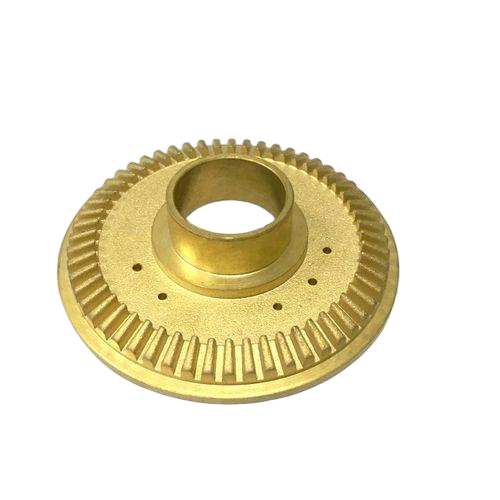
Checking a replacement gear specification
A replacement investigation should start with the assembly, not an isolated gear photograph. Record which member failed, which remains in service and whether the observed wear is representative of the original tooth form. Preserve mounting references and any known operating changes before removing evidence through cleaning or rework.
Identify the data needed to reconstruct the tooth system: tooth count, pitch or module, pressure-angle definition, modifications, face width, bore and locating features. Material and final condition belong to a separate but connected part specification. They cannot be reliably inferred from the tooth silhouette.
The KHK ABCs of gears provides context for gear geometry, accuracy and manufacture. A specialist can use appropriate measurements to identify a likely system, but the result should become a controlled, approved definition before interchangeability is claimed. For the surrounding machined shaft and housing features, coordinate the replacement datums with the actual assembly rather than assuming the old bore or shoulder was correct merely because it was previously installed.
Preserve evidence of modifications around the hub and shaft interface. A replacement project may otherwise reproduce an unintended service repair rather than the original locating geometry.
Pressure-angle selection and load-path table
The comparison should distinguish geometry identification from design approval. A pressure-angle label can be known accurately while the proposed change remains unsuitable for the assembly. Conversely, incomplete historical records can leave the label uncertain even when a worn pair still rotates.
Use the table to assign each question to the evidence that can answer it. This prevents a dimensional observation from being expanded into an unsupported performance conclusion.
| Decision | Required input | What it establishes | What remains separate |
|---|---|---|---|
| Identify tooth system | Pressure angle, pitch and modifications | Nominal mating geometry | Material condition and load rating |
| Review bearing reaction | Torque, operating geometry and force model | Calculated support loads within assumptions | Dynamic behavior and service validation |
| Assess a small pinion | Count, root form and generating definition | Geometry requiring specialist review | Approved strength and life assessment |
| Approve replacement | Controlled drawing and assembly checks | Acceptance against a defined scope | Unspecified operating conditions |
The useful outcome is a traceable decision about a particular pair, rather than a general preference for a familiar nominal angle.
Worked force comparison with explicit assumptions
Assume an idealized external spur mesh transmitting a tangential force Ft = 100 N. Compare pressure angles of 20 degrees and 25 degrees using Fr = Ft tan(alpha), while holding the tangential force fixed. The resulting radial components are approximately 36.4 N and 46.6 N. These assumed inputs illustrate the force relationship and do not define an approved gear or bearing selection.
The relationship is described in the KHK gear-force reference. A different operating geometry or a helical system requires the appropriate definitions and equations. Do not treat the comparison as a prediction of vibration or a complete tooth-load calculation.
The example explains why a pressure-angle substitution can matter outside the teeth. Even if a proposed member appears to occupy the same envelope, the supporting bearings and housing must be evaluated under the intended load model. Changing tooth geometry also requires a mating-system review; the force calculation alone does not demonstrate that two gears will engage correctly.
Tooth and assembly verification
Verification should first establish that the manufactured member matches the approved tooth definition. Then check its relationship to the mounting bore or shaft datums and the assembled mating condition. A satisfactory bore diameter does not establish tooth-to-bore location or contact behavior.
Agree which measurements identify the pressure-angle and profile requirements and which assembly observations address contact or backlash. The appropriate method depends on the gear design and available metrology. A visual comparison with a catalogue illustration is not an adequate final check for a controlled replacement.
The standards and tolerances discussion can address the surrounding dimensional requirements, while specialist tooth inspection must be separately defined. Record any loaded or running test with its mounting and operating conditions. One unloaded spin test cannot validate every service condition. If only one member of a worn pair is replaced, include the retained member’s condition in the acceptance decision rather than treating it as a perfect reference.
Record the inspection method used to establish the tooth profile. Measurements intended to identify a likely historical system should be distinguished from final acceptance against the reconstructed drawing.

Pressure-angle information for the RFQ
The RFQ should distinguish a build-to-drawing part from a reverse-engineering or design-assistance task. A controlled tooth drawing defines a different scope from an old component supplied as the only reference. State which design authority will approve the final geometry and any proposed substitution.
Include the mating member, intended mounting arrangement and the required inspection deliverables. If the request covers only a blank or surrounding shaft features, identify that boundary so a quotation does not imply finished-tooth manufacture or rating work. The milling scope may cover related pockets and mounting details without establishing specialist gear-cutting capability.
For a replacement, identify whether pressure angle is confirmed, inferred or unknown in the source information, and provide the evidence behind that classification to the responsible engineer. Resolve unknown geometry before production release. A supplier’s ability to quote a familiar nominal gear size is not evidence that its proposed part matches an undocumented historical pair or the operating conditions of the existing mechanism.
FAQ
Can pressure angle be determined from a tooth photograph?
A photograph may help identify the family, but the apparent flank slope depends on viewing angle, tooth position and the involute geometry. It does not reliably establish the pressure-angle definition needed for interchangeability. Appropriate dimensional inspection and the original mating information are more useful. Where reverse engineering is necessary, record the measurement method and assumptions, then obtain approval of the reconstructed tooth specification before ordering a replacement intended to operate with the retained gear.
Why do historical drawings use different nominal pressure angles?
Gear systems evolved with different tooth forms and design practices, so an older drawing can legitimately specify a nominal angle different from a current catalogue default. The practical consequence is to preserve the original system or redesign the pair through an approved engineering process. A modern nominal angle should not replace the historical value merely because it is easier to source. Compatibility, supporting loads and the intended mounting arrangement still need review.
Does a pressure-angle change require a new housing?
Not necessarily, but the answer requires an assembly-level assessment rather than a nominal-angle comparison. The proposed pair must suit the available mounting geometry, and the bearing and housing reactions must remain acceptable. Retaining the same envelope is not enough evidence. If a redesign preserves the existing housing, document the coordinated tooth and mounting definition and the verification needed to support that choice before releasing either replacement member.
Conclusion
Pressure angle should travel with the full tooth-system definition from design through manufacture and replacement. It influences both mating geometry and force direction, so a substitution can affect bearings and housing even when the tooth count remains unchanged.
For an existing mechanism, resolve identification uncertainty before using a candidate part as the basis for acceptance. For a new design, coordinate the root geometry, modifications and mounting condition with the specialist gear review. The result is a specification that can be manufactured and inspected without guessing which tooth system the original designer intended.
6CProto’s CNC and DFM workflow can support the surrounding custom component geometry. Provide the tooth definition, mating information and mounting drawings for quotation, with specialist tooth manufacture and verification identified as scope requiring confirmation.