

A nut can stop short of its seating face even when the visible thread looks complete. The final turns may be incomplete, the mating chamfer may strike the shoulder, or the threading tool may lack room to withdraw. A thread relief groove addresses a specific clearance problem; it must also preserve the section that carries the load.
The drawing should therefore separate three lengths: full usable thread, incomplete runout and any deliberate relief. Combining them into one overall threaded length leaves the machinist, inspector and assembly team with different interpretations. This becomes especially costly when a shoulder position controls bearing preload or a sealing face.
The following review concerns relief at external shoulders and internal thread terminations. It does not supply a universal groove width based on thread pitch. The required envelope depends on the thread system, tool route, mating geometry and stress conditions. A released standard relief form can be appropriate when its scope matches the feature; otherwise the section must be dimensioned explicitly.
For a turned shaft, the relief belongs in the same discussion as CNC turning and threading. For an internal feature, access may also depend on the boring or milling sequence. In both cases, a clean assembly seat is the functional goal, not simply the presence of a groove.
What must a thread relief groove clear at the shoulder?
Relief must clear the tool and preserve the loaded section.
Define a thread relief groove from the actual thread termination, mating part and tool envelope, then check full engagement, remaining material and inspection access together before release.
An external relief reduces the shaft diameter near the shoulder. An internal relief enlarges a bore locally. Both can provide clearance, but their effects on the surrounding material are opposite. The external groove may reduce the tensile or bending section; the internal groove may reduce the wall beneath a neighboring surface.
Do not confuse workpiece relief with relief behind a cutting edge. Tapmatic's thread terminology includes tool-related relief terms, so the noun alone is ambiguous in a process discussion. Identify the feature on a section and state whether it belongs to the part or the tool.
For either location, include the mating part. Its entry chamfer and incomplete thread affect where useful engagement begins. A groove that looks adequate in the shaft model may still leave the nut bearing on an incomplete crest. Check the full stack to the seating face rather than approving the two components independently.
Separate complete thread length from tool runout
Full thread length should describe the portion with the required complete form, not every visible helical mark. Tool entry and exit can produce partial threads. A groove gives the tool somewhere to finish or withdraw, but it does not automatically extend usable engagement to the adjacent shoulder.
The threading route matters. Single-point turning uses a controlled exit path, while a tap has its own chamfered cutting lead and bottoming limitations. Thread milling has a different approach and exit envelope. Sandvik Coromant's thread-turning application guidance discusses threading strategy and burr control, reinforcing why the final passes and termination need a planned route.
On the drawing, locate the end of complete thread relative to a functional datum and show the permitted incomplete region separately. Include any required minimum engagement after the mating part seats. Do not require a full thread to extend into a space reserved for tool clearance.
Where available length is limited, review the complete joint rather than forcing the groove narrower. An alternative tool route, a changed mating chamfer or a relocated shoulder may be more defensible. The selected solution still needs verification of the load path and assembly position.
Preserve section at a fatigue-sensitive shoulder
A relief is also a geometric discontinuity. On a shaft carrying cyclic bending or tension, its bottom diameter and transition shape may become more consequential than the nominal thread length. A sharp groove corner should not be accepted solely because the tool can produce it easily.
Assess the service load path using the smallest section and the actual transition. A simple area calculation can show material removed, but it cannot establish fatigue strength. Thread roots, groove blends, surface condition, material state and residual stress all affect the result. The responsible designer should determine whether a stress analysis or application-specific test is necessary.
Avoid an unqualified instruction to make the groove as deep as possible. Depth beyond the clearance requirement removes useful material. Similarly, increasing a blend radius may consume axial clearance or interfere with a mating chamfer. These dimensions are coupled.
ASME's dimensioning and tolerancing standard scope provides the drawing framework for communicating controlled geometry, not a ready-made fatigue approval for every relief. If the application is fatigue-sensitive, identify the controlled root condition and any prohibited machining marks explicitly. General deburring instructions should not permit uncontrolled reshaping of the transition.
Reach and inspect the last required full thread
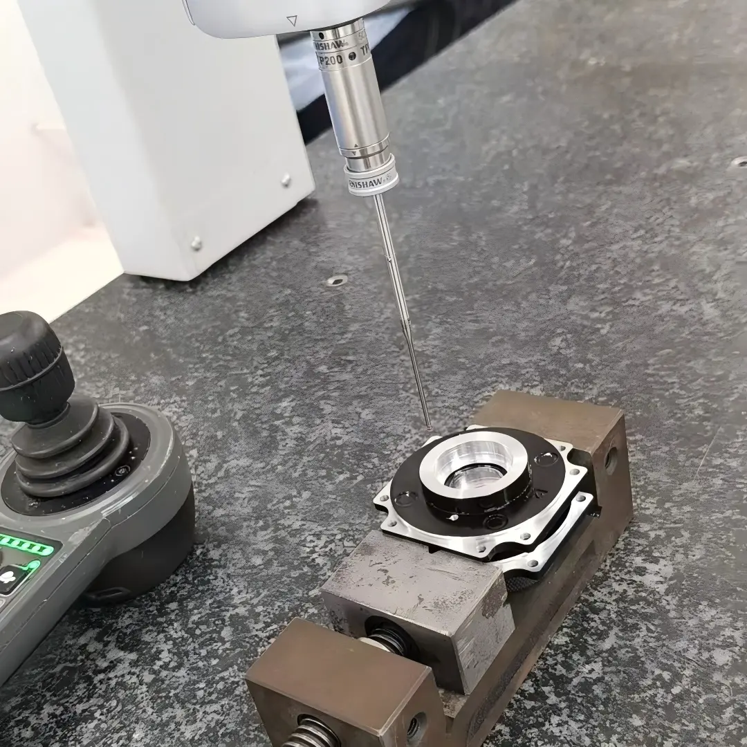
Inspection close to a shoulder has a physical access limit. A thread ring or plug gauge may verify functional fit over a reachable region without proving that the last required thread is complete. A probe may also be unable to contact the groove bottom or transition without interference.
Choose the method from the requirement. A suitable optical or profile measurement can examine the visible termination; a thread gauge checks a different set of characteristics. Internal geometry may require an appropriate access strategy or a representative section during process qualification. Do not claim that one gauge establishes every feature.
Record the distance between the datum shoulder and the boundary being inspected. If that boundary is the last full thread, define how it is identified. A photograph without scale or reference position is weak evidence for a controlled axial length.
Surface condition matters where a groove carries load or must remain free of burrs. State whether the check is visual, dimensional or both. The agreed inspection scope should distinguish thread fit, termination geometry and groove dimensions so that a passing gauge does not conceal an unmeasured critical region.
A groove section with explicit clearance and area assumptions
Use a section to make the trade-off measurable. Assume a hypothetical external thread with a nominal 16 mm major diameter and a proposed 12 mm groove-bottom diameter. The circular area at the groove is pi x 12 squared / 4 = 113.10 square mm, compared with 201.06 square mm for the 16 mm reference cylinder. The groove section is about 56.25% of that reference area.
These assumed dimensions illustrate lost section only. The reference cylinder is not the thread’s tensile stress area, and the area ratio is not a strength or fatigue ratio. No load rating follows from this calculation.
Add the axial dimensions to the same section: seating face, groove width, transition extent, last complete thread and minimum usable engagement. Show the mating chamfer in its seated position. Check that the tool’s exit envelope fits without consuming the complete thread length.
For an internal relief, repeat the exercise using the remaining wall rather than a reduced shaft. Include neighboring cross holes or counterbores that may make the local section thinner. This drawing review often reveals a clearance conflict before any numerical stress calculation is attempted.
Compare threading routes and termination checks
Different manufacturing routes create different inspection questions. A comparison should preserve the same functional target while identifying the access and evidence needed for each option. It should not convert a general route into a guaranteed capability.
| Route | Termination constraint | Drawing input | Verification focus |
|---|---|---|---|
| Single-point external turning | Tool withdrawal near shoulder | Complete length and relief envelope | Last full thread and groove section |
| Internal tapping | Tap lead and bottom clearance | Usable thread versus total hole depth | Gauge reach and bottom condition |
| Thread milling | Cutter and holder approach | Internal access and termination zone | Form, position and exit region |
| Alternative joint layout | Mating chamfer or shoulder location | Revised engagement stack | Seating and load transfer |
Sandvik Coromant's thread-milling troubleshooting reference identifies tool runout as a quality influence, but that spindle or cutter error differs from an incomplete thread runout region. Keeping the two meanings separate avoids an ambiguous corrective action. The milling process review should also include holder clearance when thread milling is proposed, since the cutting diameter alone does not establish access.
Accept the seating interface and the relief independently
Acceptance starts with the joint’s actual function. Assemble a representative mating part or use a qualified functional check to confirm that seating occurs at the intended face. A component that reaches the correct axial position only under excessive torque may be binding at the thread termination rather than seating correctly.
Confirm the usable engagement and inspect the relief dimensions against the released section. Check for burrs, damaged crests or a sharp transition that violates the drawing. If coating or heat treatment follows threading, decide which checks occur after that operation because fit and surface condition may change.
Maintain the distinction between a fit test and a strength validation. A mating nut can demonstrate clearance without establishing thread stripping resistance or fatigue life. Likewise, a destructive pull test on one sample does not identify which dimension controlled the result.
Sandvik Coromant's threading application guide supports process planning across threading methods; the specific acceptance limits must still come from the selected thread specification and component drawing. Where the drawing lacks those limits, resolve the requirement rather than allowing production inspection to invent a criterion from the available gauge.
Resolve thread-end callouts before quoting
Before quoting, identify the thread designation, pitch, class or tolerance system, handedness and complete length. Show the shoulder datum, permitted incomplete region and relief section. If a standard relief form is invoked, identify the applicable form and edition rather than leaving the supplier to choose from unrelated examples.
State the final material and surface condition. A groove that must remain free of plating buildup or a thread that will be coated needs its acceptance condition identified. Do not tighten every dimension to compensate for an undefined assembly interface.
The RFQ should also explain whether the groove is a preferred solution or a mandatory geometry. When it is only a proposed tool-clearance feature, a supplier may suggest a different route. Engineering must check the resulting engagement and section before accepting that change.
Finally, agree how inaccessible features will be verified. If an internal termination cannot be measured directly with the planned equipment, identify a suitable alternative or qualification approach before the order is released. Resolving this early is more useful than receiving a generic inspection report that lists only the easy diameters and omits the shoulder region that caused the concern.
FAQ
Can a thread sealant compensate for an incorrectly located relief?
Sealant should not be treated as a correction for missing engagement or an unintended seating gap. Its function depends on the joint and the specified sealing system, while the groove changes mechanical geometry. If leakage occurs, separate the sealing interface from the thread's locating and load-carrying functions. Confirm that the mating part seats as designed before considering a sealant change, and obtain engineering approval for any departure from the released joint specification.
Is a relief groove required on every threaded shaft?
No. The need depends on the tool route, available incomplete-thread region and mating geometry. Some joints provide adequate runout space or use a different termination arrangement. Adding a groove without a clearance requirement can unnecessarily reduce the section. Review the shoulder stack and manufacturing method first. Where a selected component standard specifies the termination, follow its applicable requirements rather than substituting a generic groove copied from another shaft.
What should happen if the supplier proposes omitting the groove?
Ask what changes in the tool path, complete thread length and mating clearance. Omission can be acceptable when the required interface and inspection outcomes remain satisfied, but it should not be an undocumented shop-floor decision. Have engineering review the revised section and acceptance method, especially for a load-bearing shoulder. Retain the approved drawing or deviation so that repeat orders use the same definition rather than alternating between two incompatible interpretations.
Conclusion
A thread relief groove should solve a visible clearance problem while preserving the joint’s loaded section. The useful design variables are the complete thread boundary, tool withdrawal space, mating chamfer, shoulder seat and remaining material. None can be replaced by a universal groove-width rule.
The strongest release combines a dimensioned section with an inspection method that can reach the critical region. Functional seating, thread fit and fatigue-related geometry are separate questions and may require different evidence. Treat changes to the groove or the threading route as changes to that combined requirement, not as isolated machining details.
To review a shoulder termination, send 6CProto the thread section, mating component, material condition and required checks. This gives the manufacturing discussion a clear target without assuming that a generic threading operation resolves every access or strength concern.
{“@context”: “https://schema.org”, “@type”: “FAQPage”, “mainEntity”: [{“@type”: “Question”, “name”: “Can a thread sealant compensate for an incorrectly located relief?”, “acceptedAnswer”: {“@type”: “Answer”, “text”: “Sealant should not be treated as a correction for missing engagement or an unintended seating gap. Its function depends on the joint and the specified sealing system, while the groove changes mechanical geometry. If leakage occurs, separate the sealing interface from the thread’s locating and load-carrying functions. Confirm that the mating part seats as designed before considering a sealant change, and obtain engineering approval for any departure from the released joint specification.”}}, {“@type”: “Question”, “name”: “Is a relief groove required on every threaded shaft?”, “acceptedAnswer”: {“@type”: “Answer”, “text”: “No. The need depends on the tool route, available incomplete-thread region and mating geometry. Some joints provide adequate runout space or use a different termination arrangement. Adding a groove without a clearance requirement can unnecessarily reduce the section. Review the shoulder stack and manufacturing method first. Where a selected component standard specifies the termination, follow its applicable requirements rather than substituting a generic groove copied from another shaft.”}}, {“@type”: “Question”, “name”: “What should happen if the supplier proposes omitting the groove?”, “acceptedAnswer”: {“@type”: “Answer”, “text”: “Ask what changes in the tool path, complete thread length and mating clearance. Omission can be acceptable when the required interface and inspection outcomes remain satisfied, but it should not be an undocumented shop-floor decision. Have engineering review the revised section and acceptance method, especially for a load-bearing shoulder. Retain the approved drawing or deviation so that repeat orders use the same definition rather than alternating between two incompatible interpretations.”}}]}