

A quieter gear mesh can require a different bearing arrangement, while a simpler tooth form can leave the system short of its acoustic objective. Comparing a spur gear vs helical gear therefore means comparing the supporting assembly, not selecting the more sophisticated-looking tooth pattern.
Spur teeth engage without the helix-generated axial thrust associated with a conventional helical mesh. Helical teeth introduce progressive engagement and a different force system, but their operating sound and suitability still depend on accuracy, load, speed, mounting and lubrication. Neither label guarantees a particular noise result or load rating.
For a custom drive, define the functional target first: the permitted sound behavior, available face width, bearing and housing constraints, and the required tooth quality. The useful comparison then shows which complete arrangement can meet those targets and what evidence is needed to accept it. General gear-family identification belongs to the broader selection guide rather than being repeated here.
How does spur gear vs helical gear contact progression differ?
Helical teeth engage progressively across their width.
Progressive helical engagement can reduce abruptness compared with spur engagement, but operating noise still depends on tooth accuracy, load, speed and the complete mounted transmission rather than tooth inclination alone.
The KHK gear-type reference describes the geometry distinction. Avoid converting that tendency into a guaranteed acoustic reduction for a custom assembly. Housing vibration, alignment and supporting components can influence the sound measured outside the gearbox, while a tooth-quality difference can invalidate a nominal like-for-like comparison.
If noise is a design driver, define the operating cases and measurement arrangement before selecting a family. Compare assemblies under equivalent load, speed and mounting conditions. An unloaded hand rotation or a short audio recording from a different enclosure does not establish the intended service result. The specification should identify the acoustic requirement as a system output and preserve the tooth and mounting conditions used during its validation, so a later manufacturing change can be assessed against meaningful evidence.
Specify whether the acoustic observation concerns a particular operating tone, a broader level or another approved criterion. Different observations should not be reduced to an informal statement that one gearbox sounds better.
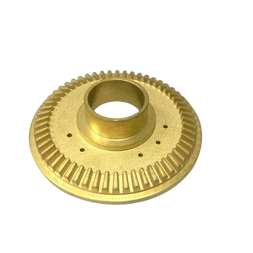
Axial thrust and bearing loads
A conventional helical mesh generates an axial force component that must be located and reacted through the bearings and housing. The shaft’s retention features and bearing arrangement therefore form part of the selection. A space claim that fits the gears alone may omit the hardware needed to carry their reaction.
The KHK helical technical reference distinguishes normal and transverse geometry as well as the helical arrangement. Identify which tooth system is being specified before applying force or dimensional relationships. For reversing operation, consider how the direction of thrust changes and whether the locating arrangement works in both directions.
Spur gearing avoids the helix-generated axial component, but it does not eliminate all bearing or alignment requirements. Radial and tangential reactions remain, and other assembly loads may still require axial restraint. Compare the actual load path from the teeth into the supporting structure. A bearing selected from a torque number alone may overlook the reaction components that distinguish the two candidate drive arrangements.
Check retention features on both sides of a reversing shaft. A locating arrangement that reacts thrust in one direction may leave the alternate operating case undefined.
Face width and packaging
Face width contributes to the contact arrangement, but it cannot be chosen independently from alignment, stiffness and the tooth design. A wider face that is poorly supported may not distribute load as the designer expects. The housing and shafts must preserve the intended relationship across the engaged width.
For helical gears, include the consequences of helix geometry and thrust restraint in the package review. For either family, identify access for assembly, adjustment, lubrication and inspection. A compact CAD envelope is not useful if a locating ring or measurement tool cannot be installed after the housing closes.
The KHK dimensional reference supplies the tooth geometry context, while the custom assembly needs its own section drawing and tolerance analysis. Mark which width is functional engagement and which features provide clearance or retention. If the design team proposes a narrower gear to recover space for bearings, revisit the tooth and load assessment rather than assume the earlier rating applies unchanged. Packaging changes can move the limiting condition elsewhere in the drive.
Tooth finishing and inspection
A family comparison should use comparable tooth-quality requirements. Comparing a finished helical gear with an unqualified spur blank confuses geometry with manufacturing scope. The tooth process, material condition and acceptance evidence need to be identified for each candidate.
The KHK ABCs of gears separates manufacture and accuracy from basic family names. Depending on the specification, a blank may need further tooth generation, heat treatment and finishing. Those operations can affect the relationship between teeth and mounting datums, so the route must preserve or restore the required geometry.
For the surrounding CNC-machined features, identify bores, journals and locating shoulders separately from specialist tooth work. Do not read a general machining service scope as confirmation of gear grinding or a particular tooth-quality class. The quotation should state exactly which tooth operations and inspection deliverables are included. That makes a cost or lead-time comparison reflect equivalent finished components rather than different stages of manufacture.
Keep final material condition in the comparison. Tooth finishing assessed before a later thermal operation may not represent the geometry delivered for assembly.
Assembly trade-off decision table
The selection should be evaluated at the system level. A benefit in engagement behavior may require additional bearing or housing work, while a simpler support arrangement may leave another performance objective unmet. Neither outcome can be assessed from tooth shape alone.
Use the table to identify the evidence needed for the dominant requirement. It intentionally avoids universal ratings for noise, efficiency or strength.
| Requirement | Spur candidate | Helical candidate | Compare using |
|---|---|---|---|
| Contact progression | Engagement characteristic of straight teeth | Progressive engagement across width | Controlled running and acoustic conditions |
| Support system | No helix-generated axial thrust | Defined thrust path required | Bearing and housing load review |
| Package | Gear, bearings and assembly access | Gear plus thrust-related support and access | Complete section and tolerance stack |
| Manufacture | Specified tooth route and quality | Specified helical system and quality | Equivalent finished-part scope |
If one candidate is rejected, record the governing reason. That makes the decision useful when a later revision changes the housing or operating target.
Worked thrust estimate with stated assumptions
Assume an idealized helical mesh with tangential force Ft = 200 N and helix angle beta = 20 degrees. Using the simplified relation Fa = Ft tan(beta), the axial component is approximately 72.8 N. These assumed values illustrate the thrust path; they do not establish a bearing rating or a complete gear load case.
The KHK gear-force reference describes the component relationships. Real design work must use the appropriate geometry, operating conditions and additional effects. Reversal can change the thrust direction, and transient loading can differ from the assumed steady condition.
For comparison, the spur candidate has no helix-generated axial component under the same idealized distinction. That does not mean its shaft can be left axially unlocated or that the helical candidate is unsuitable. The example identifies a support requirement that must appear in the bearing and housing assessment. Check the full reaction system and the intended locating arrangement before using the nominal calculation to choose hardware.
Verification of the mounted pair
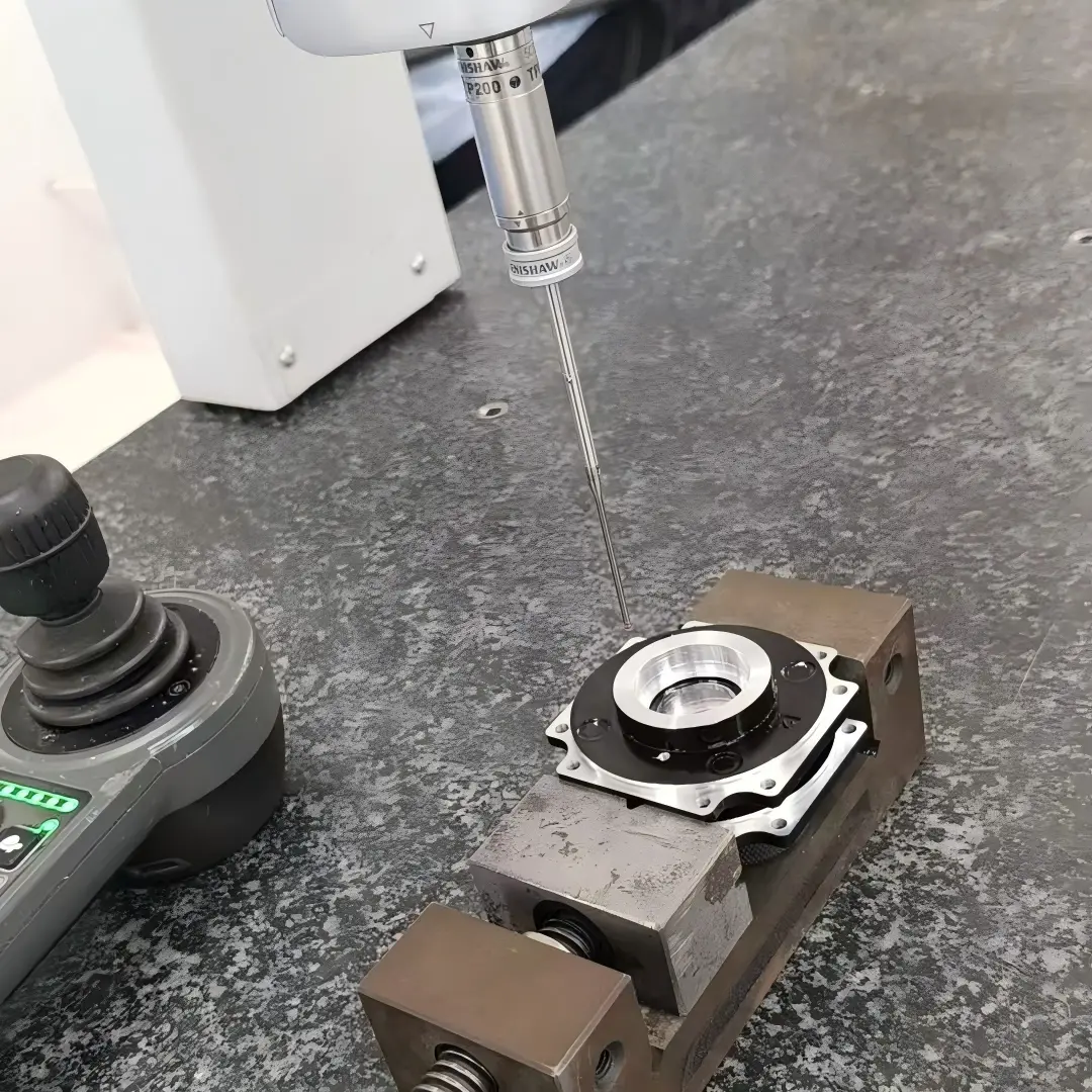
Component inspection and a running test should answer different questions. Tooth and mounting measurements establish conformance to the approved definition. A running assessment observes the assembled system under its stated condition. One cannot automatically replace the other when the project requires both.
Identify the datums that locate each gear and the adjustment method that establishes the mesh. Record backlash and any contact observations using the agreed method, but keep those results distinct from the acoustic or thermal test. A quiet unloaded mesh does not prove its behavior at the required load.
The dimensional acceptance requirements should cover the functional shaft and housing interfaces, with specialist tooth checks explicitly assigned. For a family comparison, use the same acceptance envelope where the requirements are genuinely shared. If the helical arrangement uses a different bearing system or mounting condition, state that difference in the test record rather than present the result as an isolated comparison between tooth inclinations.
Preserve the assembly preload and adjustment state during any running comparison. A change in those settings can affect the observed result without a change of gear family.
Quotation scope for the selected arrangement
The RFQ should show the complete arrangement that the supplier is expected to deliver. Identify whether it covers gears, surrounding machined components, a matched pair or an assembled drive. Include the tooth definition, material condition, mounting interfaces and required evidence without assuming those items are implicit in a family name.
For the housing, a milling review can address bore relationships, pockets and assembly access. Specialist tooth manufacture, finishing and rating require separate confirmation where they are part of the project. If acoustic validation is included, define its operating state and acceptance method so the quotation prices a real test rather than an undefined low-noise promise.
Retain the selection rationale with the released drawings. A later reduction in package width, change of bearing or revised operating speed can alter the original trade-off. The final handoff should make clear which requirements drove the family choice and which changes require renewed assessment before the next production batch.
FAQ
Are double-helical gears equivalent to a simple helical pair?
A double-helical arrangement uses opposing helix directions to address thrust within its intended geometry, but it introduces its own manufacturing, alignment and assembly requirements. It should not be treated as a drop-in version of a conventional single-helical pair. The complete tooth definition and supporting arrangement need review. A general statement about opposing thrust does not establish the residual reactions or performance of a particular custom design under all operating conditions.
Can one member of a spur pair be replaced with a helical gear?
A mating system must have compatible tooth geometry. Replacing one spur member with an unrelated helical member does not preserve the original mesh simply because tooth count and outside diameter appear similar. A change of family requires a coordinated redesign and review of the mating geometry and supporting assembly. Resolve that scope before procurement rather than treating the new part as an equivalent replacement based on a few nominal dimensions.
Should the noise requirement be placed on the loose gear drawing?
A loose gear drawing can control geometry and other characteristics that contribute to operation, but sound measured from a running gearbox depends on the assembled system and test condition. Define the relevant requirement at the appropriate assembly level and connect it to the component specifications. If a supplier is responsible only for a gear, distinguish its deliverables from any system acoustic validation that another party must perform after installation.
Conclusion
The spur-versus-helical choice is complete only when the tooth behavior, bearing reaction and available package support the same operating target. Progressive engagement can be valuable, but its benefit must be assessed with the thrust path and equivalent manufacturing quality.
Compare finished arrangements under defined conditions and preserve the selection rationale with their drawings. This prevents a later geometry or support change from retaining an approval that belonged to a different assembly. A family name remains a starting point, not the performance specification.
6CProto’s CNC and DFM workflow can support the associated custom components. Send the assembly section, tooth definition and acceptance requirements for quotation, separating surrounding machining from specialist gear manufacture and running validation where those services need confirmation.
{“@context”: “https://schema.org”, “@type”: “FAQPage”, “mainEntity”: [{“@type”: “Question”, “name”: “Are double-helical gears equivalent to a simple helical pair?”, “acceptedAnswer”: {“@type”: “Answer”, “text”: “A double-helical arrangement uses opposing helix directions to address thrust within its intended geometry, but it introduces its own manufacturing, alignment and assembly requirements. It should not be treated as a drop-in version of a conventional single-helical pair. The complete tooth definition and supporting arrangement need review. A general statement about opposing thrust does not establish the residual reactions or performance of a particular custom design under all operating conditions.”}}, {“@type”: “Question”, “name”: “Can one member of a spur pair be replaced with a helical gear?”, “acceptedAnswer”: {“@type”: “Answer”, “text”: “A mating system must have compatible tooth geometry. Replacing one spur member with an unrelated helical member does not preserve the original mesh simply because tooth count and outside diameter appear similar. A change of family requires a coordinated redesign and review of the mating geometry and supporting assembly. Resolve that scope before procurement rather than treating the new part as an equivalent replacement based on a few nominal dimensions.”}}, {“@type”: “Question”, “name”: “Should the noise requirement be placed on the loose gear drawing?”, “acceptedAnswer”: {“@type”: “Answer”, “text”: “A loose gear drawing can control geometry and other characteristics that contribute to operation, but sound measured from a running gearbox depends on the assembled system and test condition. Define the relevant requirement at the appropriate assembly level and connect it to the component specifications. If a supplier is responsible only for a gear, distinguish its deliverables from any system acoustic validation that another party must perform after installation.”}}]}