

A replacement gear can match the old outside diameter and still fail to mesh correctly. With intersecting shaft drives, the tooth geometry is only part of the specification: the mating member, shaft angle and installed position determine whether the pair works together. The useful bevel gear vs miter gear distinction is that a miter pair is a particular bevel gear arrangement with equal tooth counts and a 1:1 speed ratio, commonly at a right angle.
That definition does not make every right angle bevel pair interchangeable. This guide follows the specification from ratio and shaft layout through mounting distance, contact pattern and drawing evidence. It addresses a custom mechanical assembly rather than assuming that a catalog gear or a visually similar replacement has the required load capacity.
Bevel gear vs miter gear: what makes a miter pair?
Equal tooth counts give a miter pair its 1:1 ratio.
Specify the shaft angle as well as equal tooth counts; the familiar right angle miter arrangement is a particular geometry, not a universal replacement rule.
Bevel gears transmit motion between intersecting shaft axes using conical reference geometry. A miter pair uses equal tooth counts so the magnitude of the speed ratio is one. KHK’s gear type guide places miter gears within the bevel family, while its miter gear technical information shows that installation requirements remain product specific.
Separate tooth form from ratio. Straight and spiral describe tooth geometry, while miter describes the equal ratio arrangement. A spiral miter member cannot be selected merely by matching module and bore to a straight tooth member. The intended mating geometry and, for spiral forms, the matching hand and design system matter. Identify the pair first, then review individual members and their mounting features.
A replacement pair also needs compatible bore and retention details. Equal tooth counts do not define the shaft fit, keying or axial location required by the surrounding mechanism.
Shaft angle and ratio
The ratio follows the tooth counts, but the shaft angle determines the pitch cone geometry. In an idealized pair, speed magnitudes satisfy n1/n2 = z2/z1. Equal tooth counts therefore preserve speed magnitude, while unequal tooth counts change it. Direction of rotation must still be checked in the actual assembly rather than inferred from a single loose gear.
A right angle gearbox with a 20 tooth driving member and a 40 tooth driven member is a bevel reduction pair, not a miter pair. Changing to equal tooth counts changes more than the output speed: pitch cone angles, envelope and possibly the housing interfaces change as well. KHK’s gear dimension calculations explains the geometric relationships behind these distinctions.
Record the included angle between shaft axes, the location of their theoretical intersection and the direction in which each shaft projects. A layout sketch with shaft datums is more reliable than an instruction to “turn the drive through 90 degrees.” Check that bearing arrangements and assembly access fit the chosen cone geometry.
Check the required direction from a clear input and output orientation sketch. A reversed installation can change the assembly behavior even when the numerical speed ratio remains correct.
Mounting distance and contact pattern
Mounting distance locates the gear relative to the shaft intersection and mating member. It is not simply the distance from a convenient hub face to the nearest bearing. A gear seated against the wrong shoulder can have apparently acceptable backlash at one location while showing poor tooth contact across its face.
Use the manufacturer’s reference surfaces and assembly dimensions for a catalog pair, or establish equivalent references in a custom design. KHK’s ground spiral miter drawing information illustrates how mounting dimensions accompany tooth and bore data. Its stated product values apply to that catalog design, not to every custom bevel pair.
During assembly, examine contact under a controlled checking method and compare it with the approved criterion. Distinguish a marking check from proof of capacity under full duty. Housing alignment, bearing deflection and thermal growth can shift operating contact. If a shim changes mounting distance, record the resulting backlash and contact together; optimizing only one observation can move the other outside its intended range.
Retain the checking condition with the contact record, including bearing support and assembly adjustment. An unreferenced photograph cannot show how the pair was positioned during the observation.
Specifying a custom replacement pair
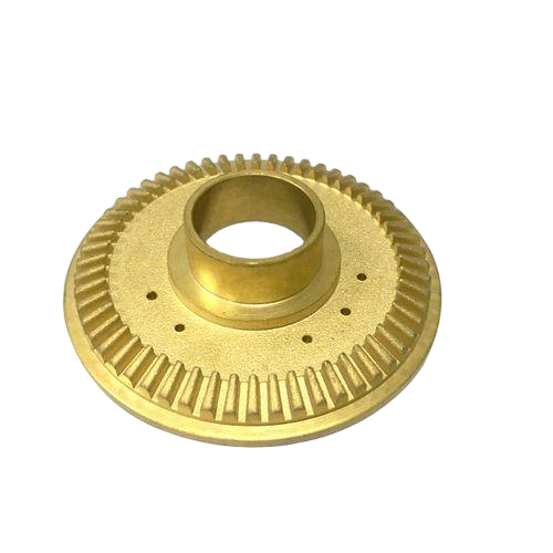
A replacement request should identify both members, even when only one is damaged. An isolated gear drawing may omit the information that makes the pair compatible. Preserve manufacturer markings, tooth counts, mounting references, shaft angle, tooth form and available mating geometry before dismantling evidence is lost.
If the original design is unavailable, separate measured observations from calculated or assumed values. A scan or tooth impression can support an investigation, but it does not automatically recover the original generating geometry or inspection class. For worn parts, estimate the effect of wear before treating the measured flank as the intended shape.
Explain the failure as well as the requested replacement. Local pitting, edge contact, broken teeth and loose bearing seats may call for different corrective work. A custom component machining review can address the body, bore and housing interfaces; it should not be read as a claim that every specialized tooth generating or finishing process is available or already approved for the job.
Where only worn samples exist, mark uncertain dimensions explicitly. A nominal reconstructed from damaged teeth should not be released as an original design value without engineering approval.
Load and geometry decision table
Choose the arrangement with the shaft layout and load path in view. Ratio alone does not decide the bearing loads, noise behavior or suitable manufacturing route. The table identifies information that changes the decision; it does not assign universal performance rankings to tooth forms.
| Decision | Miter pair | Unequal ratio bevel pair | Evidence needed |
|---|---|---|---|
| Speed relationship | Equal tooth counts, 1:1 magnitude | Ratio follows tooth counts | Input speed, output requirement |
| Shaft layout | Specify included angle explicitly | Specify included angle explicitly | Axis and intersection drawing |
| Installation | Pair specific mounting distance | Pair specific mounting distance | Reference surfaces and shim scheme |
| Load support | Check forces and housing stiffness | Check forces and housing stiffness | Torque, duty and bearing arrangement |
KHK’s gear force reference shows why force components belong in the assembly assessment. Do not select a bearing only from transmitted torque or assume that a 1:1 pair produces no axial reaction. The final load calculation must use the actual geometry and tooth form.
Include reversible duty in the review where relevant. The loaded flank and supporting reactions can change with direction, so a favorable one direction result has a defined boundary.
Worked drawing example with explicit assumptions
Assume a hypothetical right angle drive must turn an output shaft at the same speed magnitude as a 600 rpm input. Select equal tooth counts for a miter arrangement; if both members have 24 teeth, the ideal ratio is 24/24 = 1 and the output speed magnitude remains 600 rpm. This calculation establishes the speed relationship only.
Now add a second requirement: a driven device must instead run at 300 rpm. A 24 tooth driver and 48 tooth driven member provide an ideal 2:1 reduction, giving 600 x 24/48 = 300 rpm. The pitch cone geometry and space claim must be recalculated; simply enlarging the old driven member within an unchanged housing is not an approved design.
For either case, the drawing should show the shaft intersection, mounting references and room for bearing support. Torque capacity, tooth strength, lubrication and thermal duty remain separate checks. No load rating is implied by the chosen tooth counts. Review the revised geometry before releasing the housing or replacement pair for manufacture.
If the shafts do not actually intersect at the intended point, the assumed bevel geometry no longer describes the installed arrangement. Check the layout before refining tooth details.
Tooth and assembly verification checklist
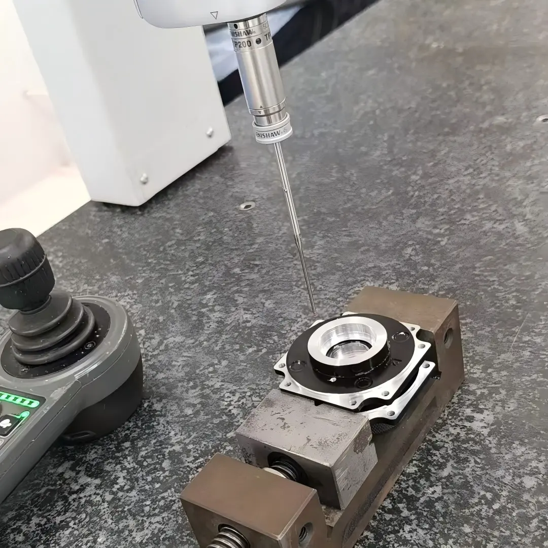
Inspection should distinguish individual geometry from assembled performance. Tooth count, bore dimensions and hub runout are useful checks, but they cannot alone demonstrate correct engagement. Record the specified reference axis, relevant mounting face and the relationship between the tooth geometry and those datums.
An assembly check should include the intended bearing condition, mounting distance, backlash and tooth contact observation. Follow a documented procedure for applying marking compound and rotating the pair so that repeated results can be compared. KHK’s backlash guidance explains that backlash is an intentional operating characteristic, not simply a defect to eliminate.
Use the required inspection framework for the actual design; KHK’s gear fundamentals reference is useful background but does not confer a grade on an unmeasured replacement. Keep the report connected to the drawing revision and pair identification. Through agreed dimensional inspection requirements, define which body and mounting dimensions need individual results and which assembled observations require a separate approval.
Check rotation through the required range rather than inspecting one convenient mesh position. Localized tightness or contact variation may be missed by a single static observation alone.
Information to include in a custom component RFQ
Package the two gear drawings with the assembly layout, not as unrelated individual components. Include tooth system, counts, ratio, shaft angle, mounting distance references, face width, bore and retention details. State the material and required condition without relying on the color or hardness of a worn original.
Provide the duty information needed for engineering review: torque direction, speed range, reversals, shock loading, lubrication and surrounding temperature. If these are not yet known, identify the unresolved requirement before a manufacturing assumption becomes a design requirement. Define whether the scope is a reproduction, a compatible replacement or a redesigned assembly; each calls for different evidence.
Housing interfaces often need their own review. Discuss milled bearing seats and mounting features together with the gear layout so that access, datums and assembly order are consistent. Request a documented disposition for deviations from the mating geometry. A supplier’s ability to machine a hub does not by itself establish a qualified process for its teeth.
Identify which inspection results accompany the delivered pair and which remain assembly responsibilities. This avoids treating a gear body report as proof of installed contact and backlash.
FAQ
Where would a miter gear be useful?
A miter pair is useful when intersecting shafts must change direction while preserving speed magnitude. Examples include mechanical transfers where the input and output axes cannot remain collinear. The application still requires a load and bearing assessment, a suitable lubrication arrangement and room for mounting adjustment. A 1:1 ratio says nothing about allowable torque or service life. Confirm the complete shaft layout before choosing a particular straight or spiral tooth arrangement.
Can one damaged miter gear be replaced on its own?
Possibly, but compatibility must be demonstrated with the remaining member. Identify the tooth system, count, geometry and manufacturer information, then inspect the condition of the mate and its support. A new member may not run acceptably against a worn or differently generated flank. For a matched or specially finished pair, replacement instructions may require both members. Do not use outside diameter and bore alone as the acceptance criteria for a single replacement.
Does zero backlash give the best bevel gear assembly?
No universal zero backlash target applies. Operating clearance accommodates geometry, lubrication, temperature and the assembly conditions specified by the design. Removing clearance without evaluating the whole pair can create tight spots or poor contact. Use the approved backlash requirement and measurement method at the specified condition, then confirm tooth contact and free rotation. If the result varies excessively around the rotation, investigate alignment and geometry rather than tightening the assembly to hide the variation.
Conclusion
A miter gear pair answers a specific ratio requirement within the broader bevel gear family. Equal tooth counts establish 1:1 speed magnitude, but shaft angle, mating geometry and mounting position determine whether that answer can work inside the assembly. Replacement decisions should therefore start with the pair and its support, then move to the individual gear drawings.
Preserve the shaft intersection and mounting references, compare backlash with contact rather than in isolation, and keep tooth verification separate from body dimensions. This approach makes a specification review more useful than a visual match to an old part. For a custom component or housing review, submit the drawings, mating arrangement and duty requirements for quotation. Specialized tooth production and verification requirements should be agreed explicitly before manufacturing release.
{“@context”: “https://schema.org”, “@type”: “FAQPage”, “mainEntity”: [{“@type”: “Question”, “name”: “Where would a miter gear be useful?”, “acceptedAnswer”: {“@type”: “Answer”, “text”: “A miter pair is useful when intersecting shafts must change direction while preserving speed magnitude. Examples include mechanical transfers where the input and output axes cannot remain collinear. The application still requires a load and bearing assessment, a suitable lubrication arrangement and room for mounting adjustment. A 1:1 ratio says nothing about allowable torque or service life. Confirm the complete shaft layout before choosing a particular straight or spiral tooth arrangement.”}}, {“@type”: “Question”, “name”: “Can one damaged miter gear be replaced on its own?”, “acceptedAnswer”: {“@type”: “Answer”, “text”: “Possibly, but compatibility must be demonstrated with the remaining member. Identify the tooth system, count, geometry and manufacturer information, then inspect the condition of the mate and its support. A new member may not run acceptably against a worn or differently generated flank. For a matched or specially finished pair, replacement instructions may require both members. Do not use outside diameter and bore alone as the acceptance criteria for a single replacement.”}}, {“@type”: “Question”, “name”: “Does zero backlash give the best bevel gear assembly?”, “acceptedAnswer”: {“@type”: “Answer”, “text”: “No universal zero backlash target applies. Operating clearance accommodates geometry, lubrication, temperature and the assembly conditions specified by the design. Removing clearance without evaluating the whole pair can create tight spots or poor contact. Use the approved backlash requirement and measurement method at the specified condition, then confirm tooth contact and free rotation. If the result varies excessively around the rotation, investigate alignment and geometry rather than tightening the assembly to hide the variation.”}}]}