

A worm driven mechanism may resist being turned by hand while still backdriving under vibration, changed lubrication or an operating load. Worm gear self locking is a conditional friction behavior, not a guaranteed substitute for a brake. The important question is whether the complete mechanism will hold under every relevant condition, including conditions different from the bench test.
This guide separates static resistance from dynamic motion, explains why lead angle and friction must be considered together, and shows how to specify a validation boundary. Where unintended motion could injure someone or damage equipment, the holding function needs a responsible safety assessment and appropriate independent protection rather than reliance on a generic worm gear label.
What determines worm gear self locking?
Lead angle and available friction act together.
A worm pair can resist backdriving under particular conditions, but geometry alone cannot guarantee holding when friction, lubrication, vibration and operating state change during the mechanism’s service.
The simplified friction model compares lead angle with an effective friction angle. It is useful for understanding the tendency, not for certifying a complete mechanism. KHK’s worm gear calculation reference discusses self locking while identifying the role of friction and operating conditions.
Specify the actual worm geometry, including starts, diameter and lead, rather than assuming that a high nominal ratio proves locking. Ratio also depends on wheel tooth count, so two pairs with similar ratios can have different lead geometry. Use the manufacturer’s defined parameters when assessing a catalog pair. For a custom design, the model must reflect the actual tooth system and operating contact rather than an isolated schematic screw.
Check terminology when comparing catalogs. Lead angle, ratio and number of starts are related parameters, but none should replace the specific geometry required by the selected calculation method alone.
Lubrication and wear effects
Lubrication reduces wear and supports the intended operation, but it can also change the friction on which a holding assumption depends. A mechanism that resists reverse motion when dry may behave differently after lubrication, warming or running in. Deliberately withholding lubrication to promote locking is not a validated substitute for a suitable holding system.
Wear, surface condition and contamination can change behavior over time. Static friction at rest and friction during motion are not necessarily the same. KHK’s worm gear pair guidance explains why self locking depends on more than a simple ratio designation.
Define the lubricant, temperature range, service interval and relevant life condition in the engineering review. If holding was tested only on new, cold parts, record that limitation. Consider whether a lubricant substitution or maintenance change alters the original evidence. Keep holding performance and wear life as separate requirements: improving one observation at a single test point does not establish the other throughout service.
Record any seals or bearing drag that contribute to a bench result. Their resistance may change with temperature and wear and should not be mistaken for gear tooth self locking.
Static holding versus dynamic motion
Static holding means resisting an applied reverse load while initially at rest. Dynamic behavior includes what happens after motion starts, during vibration or when a load changes suddenly. A pair that does not move during a gentle static test may continue moving once disturbed if the available friction changes.
Separate commanded stopping from unpowered holding. The motor, drive electronics, reduction train and external load all contribute to the actual response. A powered servo holding position does not prove passive self locking, and a static gear test does not establish stopping distance or emergency behavior.
KHK’s gear fundamentals handbook provides the broader mechanical context, including worm gear operation. For the real assembly, identify whether a brake, lock or other device carries the required holding function. Specify release and re-engagement behavior as well as capacity. The responsible design review should address credible loss of power and mechanical faults rather than assuming that a gear pair’s reluctance to turn by hand resolves the safety function.
Include the effect of stored energy in the mechanism assessment. A spring or compliant load path can drive motion differently from a gently applied static external torque during testing alone.
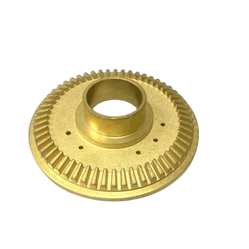
Validation before relying on holding behavior
Validation should cover the conditions that can reduce holding resistance, not only those that make it easy to demonstrate. Identify load direction, magnitude, shock, vibration, temperature, lubrication and relevant wear state. Define the permitted movement and observation time so that “did not backdrive” has a measurable meaning.
Use an approved test fixture and procedure that contains the load safely. A bench experiment with an unsupported suspended mass is not an adequate qualification method. For a critical holding function, test the complete intended system and its independent protection as required by the responsible assessment.
Include the bearing and housing arrangement because misalignment and deflection affect the gear contact. KHK’s gear force reference helps frame the supporting load paths. Record the distinction between a design calculation, a component test and a complete system validation. Passing one cannot be relabeled as the others, and evidence from a small unlubricated sample should not be extended automatically to a lubricated production assembly.
Define test termination and containment before loading the mechanism. The procedure must remain controlled if backdriving begins, rather than relying on an observer to catch the moving assembly afterward.
Load and geometry decision table
Use a decision table to reveal assumptions that can otherwise remain hidden behind the term self locking. The evidence column should describe the actual tested condition rather than a generic supplier statement. No single row establishes the complete holding function.
| Condition | Question | Required evidence |
|---|---|---|
| Geometry | What are the lead and tooth system? | Controlled gear drawing or catalog identity |
| Lubricated static load | Does reverse motion begin? | Defined load, temperature and dwell test |
| Disturbance | What happens under vibration or shock? | Contained system level validation |
| Service condition | Does behavior change with wear? | Relevant life condition evidence |
| Critical holding | What prevents hazardous movement? | Approved independent holding strategy |
The surrounding structure also needs a manufacturing definition. A machined component review can address shafts, housings and mounting features, but it does not certify a self locking or braking function. Keep the system requirement separate from the ability to produce its individual geometry.
Keep required holding evidence distinct from a general efficiency claim. A drive can transmit motion acceptably in one direction without establishing the reverse load behavior required for the application.
Worked drawing example with explicit assumptions
For a simplified hypothetical comparison, assume an effective friction coefficient of 0.10. The corresponding friction angle is arctan(0.10), approximately 5.71 degrees. A 4 degree lead angle appears on the resisting side of a simple lead versus friction angle comparison. This is an explanatory model, not a released holding calculation.
Now assume the effective coefficient falls to 0.05. Its friction angle becomes approximately 2.86 degrees, below the same 4 degree lead angle. The geometry has not changed, yet the simplified conclusion changes. The assumed coefficients are illustrative and are not recommended design values for any material or lubricant.
Real gear contact needs the applicable geometry and friction model, followed by validation. The example shows why an unspecified friction value cannot support a guarantee. Add temperature, vibration and the transition into motion to the test plan. If the assembly must hold a load independently, provide a defined holding device rather than selecting the favorable coefficient from a range.
The simplified threshold can be especially misleading near equality. Small uncertainty in friction or geometry can change the predicted tendency, so a narrow calculated margin needs careful engineering review.
Tooth and assembly verification checklist
Verify geometry and assembly condition before interpreting a holding result. Record the gear identity, shaft support, center distance, alignment and lubrication. Examine the intended tooth contact and relevant clearances; binding caused by a misaligned housing can imitate holding while producing an unacceptable drive.
KHK’s backlash reference helps distinguish intended clearance from an attempt to eliminate movement through tight assembly. A low backlash result does not demonstrate self locking, and excessive preload or interference should not be used as an undocumented brake.
For custom housings, define the relationship of bearing seats and shaft axes through the dimensional inspection requirements. A milling review of mounting and bearing features can identify datum and access issues. Keep the measured dimensions with the test sample record so that a later holding change can be investigated without guessing whether geometry, lubricant or duty changed. Inspect after testing where wear or damage could explain an apparent shift in behavior.
Inspect bearing seats and retention after a holding trial where movement occurred. A shifted support can change the apparent result and should be distinguished from tooth friction behavior in service.
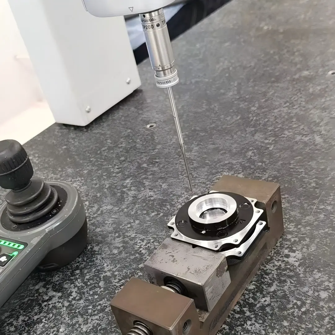
Information to include in a custom component RFQ
An RFQ should identify the gear geometry and mating arrangement, but the holding requirement needs its own specification. State whether it concerns static resistance, permitted creep, stopping, power loss or another system function. Include load direction, duty, lubrication and temperature as appropriate, plus the approved acceptance procedure.
For a replacement, supply information about both members and the housing rather than a worn wheel alone. Document whether the original mechanism relied on a separate brake or lock, and do not remove that protection because a replacement pair seems difficult to backdrive manually. Any proposed change should be reviewed at the system level.
Clarify who owns design validation, specialized gear production and functional testing. A component quotation should not be interpreted as acceptance of an unspecified safety function. Preserve the qualified process, material and assembly records with the released drawings. Changes in lubricant, surface condition or support can affect the holding evidence even when the nominal gear ratio remains unchanged.
State whether the requested scope includes a complete mechanism or only manufacturing defined components. This prevents a quotation for parts from being interpreted as approval of an unspecified holding function.
FAQ
Do all worm gears self lock?
No. Backdriving depends on the actual geometry and available friction, along with lubrication, operating state and disturbances. A high reduction ratio or a single start worm does not by itself establish a guaranteed holding function. Check the applicable manufacturer guidance and validate the complete assembly under relevant conditions. Where unintended movement has serious consequences, use the responsible safety assessment to define an appropriate independent holding strategy rather than assuming that the worm pair supplies it.
Can hand turning prove that a worm drive will hold?
A hand test can reveal gross behavior in that particular condition, but it does not establish performance under the rated load, vibration, warmed lubricant or service wear. It may also be affected by bearing drag, seals or misalignment unrelated to the intended gear friction. Use a defined, contained validation procedure with measurable movement limits and relevant conditions. Keep the observation as a limited test result rather than turning it into an unrestricted self locking claim.
Does a motor brake make the worm geometry irrelevant?
No. The brake and gear train still form a system with load paths, backlash, compliance and possible failure modes. A brake must be selected and validated for its actual holding or stopping function, while the gear assembly must meet its own geometry, lubrication and duty requirements. Assess how loads reach the brake and what occurs during engagement, release and power loss. An independent device reduces reliance on uncertain friction only when its integration is properly engineered and verified.
Conclusion
Treat self locking as behavior to evaluate under defined conditions, rather than a property guaranteed by the words worm gear. Lead geometry and friction provide a starting model; lubrication, motion, temperature, wear and disturbances determine whether that model represents the assembly in service.
Separate geometry checks, component tests and system holding validation. Do not count binding or a difficult hand turn as evidence of a qualified protection function. Where holding is critical, establish an appropriate independent strategy through the responsible engineering assessment. For custom supporting components, provide the drawings, mating arrangement and defined manufacturing scope for quotation. Keep any gear performance or holding qualification requirements explicit so that component production is reviewed against a measurable and properly bounded specification.
{“@context”: “https://schema.org”, “@type”: “FAQPage”, “mainEntity”: [{“@type”: “Question”, “name”: “Do all worm gears self lock?”, “acceptedAnswer”: {“@type”: “Answer”, “text”: “No. Backdriving depends on the actual geometry and available friction, along with lubrication, operating state and disturbances. A high reduction ratio or a single start worm does not by itself establish a guaranteed holding function. Check the applicable manufacturer guidance and validate the complete assembly under relevant conditions. Where unintended movement has serious consequences, use the responsible safety assessment to define an appropriate independent holding strategy rather than assuming that the worm pair supplies it.”}}, {“@type”: “Question”, “name”: “Can hand turning prove that a worm drive will hold?”, “acceptedAnswer”: {“@type”: “Answer”, “text”: “A hand test can reveal gross behavior in that particular condition, but it does not establish performance under the rated load, vibration, warmed lubricant or service wear. It may also be affected by bearing drag, seals or misalignment unrelated to the intended gear friction. Use a defined, contained validation procedure with measurable movement limits and relevant conditions. Keep the observation as a limited test result rather than turning it into an unrestricted self locking claim.”}}, {“@type”: “Question”, “name”: “Does a motor brake make the worm geometry irrelevant?”, “acceptedAnswer”: {“@type”: “Answer”, “text”: “No. The brake and gear train still form a system with load paths, backlash, compliance and possible failure modes. A brake must be selected and validated for its actual holding or stopping function, while the gear assembly must meet its own geometry, lubrication and duty requirements. Assess how loads reach the brake and what occurs during engagement, release and power loss. An independent device reduces reliance on uncertain friction only when its integration is properly engineered and verified.”}}]}