

A gear quotation can look complete while leaving the most important operation undecided: how the final tooth surface will be produced and checked. Comparing gear manufacturing methods means connecting tooth access, required accuracy, material condition and order quantity. A low tooling charge has little value if the selected route cannot reach a shoulder or preserve the relationship between the teeth and bearing bore.
For an engineering team, the useful output is a process envelope. It should identify which surfaces establish the gear axis, where a cutter or wire enters and exits, which operations precede heat treatment, and how the finished teeth will be accepted. Those requirements separate an assembly prototype from a transmission component expected to carry repeated load.
The comparison below concerns cut metallic gears, particularly external and internal cylindrical features. It does not select gear geometry, calculate fatigue life or imply that every general machining shop owns specialist generating and finishing equipment. The surrounding blank, hub and mounting features belong to the wider CNC machining scope; tooth production needs its own explicit agreement. Keeping those two scopes visible makes a prototype quotation easier to compare with a later repeat order.
How do gear manufacturing methods change the tooth surface?
Choose generation or form cutting by tooth requirement.
Generating methods coordinate cutter and blank motion, while form cutting follows individual tooth spaces; the appropriate route depends on profile, access, batch quantity and final inspection requirements.
A hob creates an involute through coordinated motion rather than tracing one finished tooth space with a single matching cavity. Form milling cuts spaces individually with a suitable cutter or a programmed path. This distinction affects tooling flexibility, indexing and the evidence needed to establish tooth geometry. Sandvik Coromant's gear manufacturing guide distinguishes continuous generating processes from tooth-by-tooth approaches.
Shaping adds a reciprocating generating option, useful where tool access differs from an external hob. Wire EDM instead follows an electrically generated contour through a conductive workpiece; its feasibility depends on an accessible wire path and the required tooth surface condition. Do not equate a two-dimensional outline matching CAD with verified involute accuracy across the face width.
Specify the required outcome before requesting a preferred method. An interchangeable gear pair may need controlled pitch and lead as well as an attractive tooth profile. A mechanism demonstrator might justify a different inspection scope, provided its test conclusions remain limited to that scope.
Generating and form-cutting access at internal and external teeth
Internal teeth change the access problem before they change the quotation. An external cutter may have room beyond both gear faces, while an internal ring presents a bore, a neighboring shoulder and a restricted tool body envelope. The entry opening must accommodate the complete tool assembly, not only its nominal cutting diameter.
Draw axial approach and overtravel zones on a section. Hobbing an external gear beside a flange can require clearance that is absent from the finished model. Shaping needs a stroke and exit arrangement compatible with the internal geometry. Skiving is another generating approach, but machine synchronization and tool setup are process-specific; it is not automatically available on any five-axis machine. The manufacturer's internal-gear skiving demonstration explains the coordinated cutting arrangement.
For wire EDM, identify whether the wire can pass completely through the tooth region and how it will be threaded. A blind internal gear cannot be treated like a through ring. If access forces a design change, assess the altered shoulder or split component as an assembly decision, not a cosmetic manufacturing concession. Also identify surfaces that must remain untouched during tool approach.
Tooling reuse when prototype quantities or profiles change
Prototype economics depend on preparation that may never appear in the machine cycle time. A special cutter, indexing fixture, tooth program or specialist inspection setup can dominate a small order. The relevant question is whether that preparation remains useful after the next design revision.
For a changing tooth count or profile, ask how tooling and programming change. A form cutter may cover only a defined geometry range; a flexible programmed route still needs geometry validation. Sandvik Coromant's agile gear manufacturing brochure describes a software-driven alternative to dedicated profile tools, illustrating why tooling strategy belongs in the comparison without establishing any universal savings.
Separate a geometry trial from a load-bearing pilot lot. The former can test mounting clearance and assembly sequence; the latter needs the selected material state, tooth finish and acceptance conditions. A cheap trial route should not silently become the production baseline.
Ask suppliers to identify retained fixtures, program ownership, cutter availability and repeat setup requirements. The blank may use conventional CNC milling operations, but repeat tooth cutting still depends on the agreed specialist route. Compare both the first lot and a defined repeat quantity instead of assuming that either route wins at every volume.
Inspect the tooth surface after its final operation
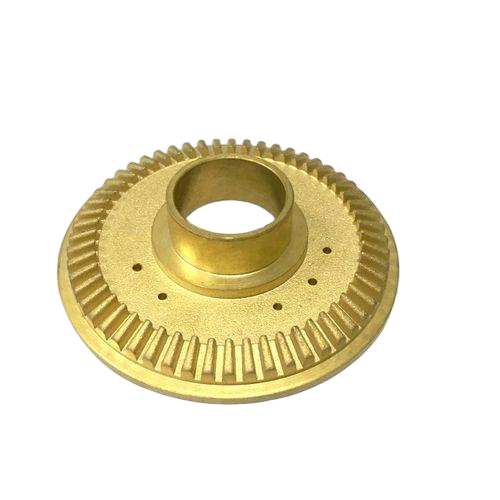
Inspection should follow the last operation capable of changing the teeth. Heat treatment can alter geometry; subsequent finishing can alter flank form, texture and the relationship to the bore. A report made on a soft blank cannot certify the finished gear.
Agree the measured characteristics individually. Tooth profile, pitch, lead or helix, tooth thickness and runout answer different questions. The terminology in KHK's gear reference handbook helps distinguish these characteristics. A single outside-diameter measurement does not substitute for them, and a smooth hand-rolled mesh does not establish a specified accuracy grade.
Define the datum used for inspection. If the gear runs on a finished bore, checking teeth relative to a temporary manufacturing center can hide an assembly error. Include the condition of the keyway, hub face and retention interface when they locate the gear in service.
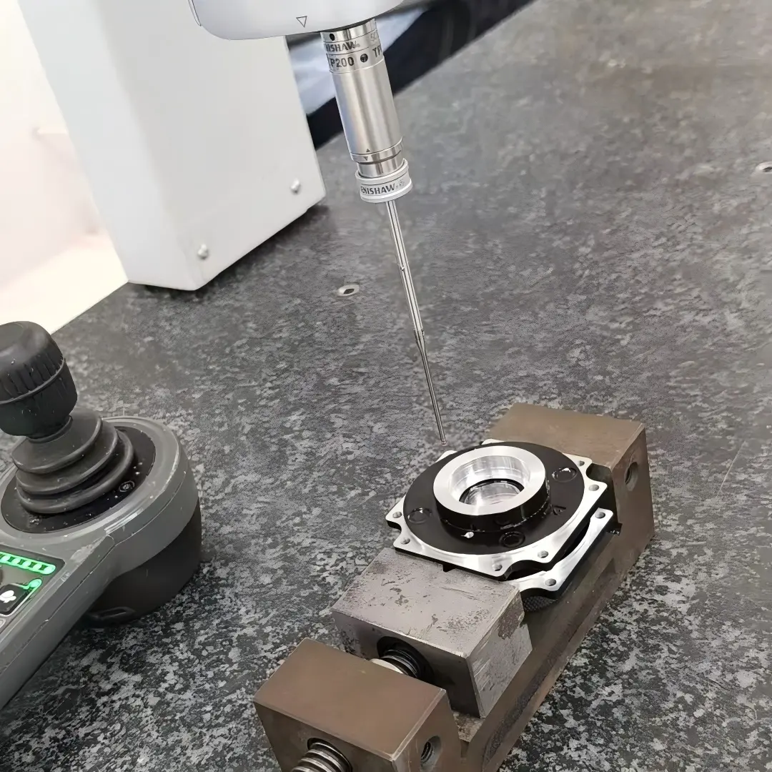
Where specialist gear metrology is required, request the proposed method before placing the order. General dimensional inspection and tooth-specific evaluation may be different operations. A supplier should state which results will be reported rather than relying on an unspecified claim of precision. The acceptance document should also identify whether surface integrity is relevant to the application.
Compare tooth-production routes by geometry and evidence
The strongest comparison combines geometry and evidence. Method names alone leave too much room for incompatible assumptions about access, preparation and finishing. The following table is a screening aid; machine and tooling suitability still require review of the actual gear.
| Route | Access question | Small-lot consideration | Acceptance concern |
|---|---|---|---|
| Hobbing | Can the hob approach and overtravel beyond the tooth face? | Hob availability and setup matter | Generated profile, pitch and final condition |
| Shaping | Is there room for the stroke and cutter exit? | Cutter and indexing preparation | Tooth geometry near restricted shoulders |
| Form or programmed milling | Can the cutter and holder enter each space? | Flexibility versus individual-space machining | Profile approximation and indexing |
| Wire EDM | Is a through wire path available? | Conductivity, threading and contour preparation | Through-height geometry and surface condition |
Load does not directly select a cutting machine. It establishes tooth, material and surface requirements that constrain the route. Likewise, the final gear geometry must be described in the correct system: KHK's gear dimension calculations distinguish the parameters needed to reconstruct a tooth form. A model without those parameters can conceal an unintended approximation. Treat a proposed substitution as an engineering change whenever it alters the controlled tooth surface or its acceptance basis.
A 30-tooth gear drawing and two order quantities
Consider an explicitly hypothetical external spur gear: module 2 mm, 30 teeth, zero profile shift, 20-degree reference pressure angle and 12 mm face width. The standard reference diameter is d = mz = 2 x 30 = 60 mm. This calculation establishes a reference circle, not an allowable outside diameter, strength rating or manufacturing tolerance.
Assume that the gear is mounted by a finished bore and seats against one hub face. A first drawing review should connect those datums to the tooth requirements, then show the neighboring shoulder and available tool overtravel. If the shoulder prevents the proposed cutter from completing the tooth width, the options include changing the clearance, choosing another route or revising the assembly. None can be selected from the reference diameter alone.
Now assume two quantities: a small mechanism trial and a repeat pilot lot. Request separate preparation and recurring-operation descriptions. The prototype may use a flexible route while the pilot lot uses dedicated generating equipment, but both must meet the same released tooth geometry if their mesh results are to be compared. Keep any intentional material or surface differences beside the test record.
Verify the finished gear in its mounting relationship
A verification checklist should close the manufacturing-to-assembly loop. Begin with the material identity and final treatment condition, then confirm that tooth measurements reference the released mounting datums. Check that any finishing allowance has been removed from the intended surfaces rather than from a convenient neighboring feature.
During assembly, inspect seating, retention and rotation over the complete mesh cycle. Check contact and backlash under the agreed mounting conditions. KHK's backlash reference distinguishes clearance at the mesh from a general dimensional fit. A changed housing center distance can alter the assembly result even when the individual gear meets its drawing.
Record burr removal at tooth edges without allowing uncontrolled modification of the active flank. Include cleanliness and protection of finished surfaces before packaging; handling damage can be highly localized and easy to miss in an average measurement.
For an initial lot, keep individual inspection records linked to the parts used in the mechanism trial. A satisfactory assembly result on one pair does not establish interchangeability across an entire lot. The dimensional requirements and inspection scope should distinguish part acceptance, matched-pair evaluation and system validation so that each result has a clear meaning.
Define tooth-production scope in the component RFQ
An effective RFQ contains more than a STEP file and quantity. Include the gear definition, a controlled drawing, final material condition, mounting datums, mating component information and any surface requirements. Show restricted tool zones and identify whether the supplier may propose a different tooth-production route.
Separate mandatory acceptance characteristics from informative design context. Torque and duty information can help a specialist understand why a surface matters, but they do not replace the designer’s released tooth specification. Conversely, prescribing a particular machine does not relieve the supplier of meeting that specification.
Ask for clarification on heat treatment sequence, finishing, inspection method and subcontracted specialist operations where relevant. Request any proposed exceptions before order acceptance. This prevents an accessible prototype route from being interpreted as proof of a production gear process that has never been agreed.
For repeat orders, identify the revision of the tooth model, cutter or program assumptions, and retained setup items. Where a route changes between lots, decide which tooth and assembly checks must be repeated. The objective is a reproducible component definition that can survive a sourcing change, rather than a quotation dependent on undocumented shop knowledge.
FAQ
Can wire EDM make a gear from nonconductive plastic?
Conventional wire EDM requires an electrically conductive workpiece, so a nonconductive plastic gear does not follow the same process route as a metallic through profile. Plastic gear sourcing needs a separate review of machining or molding, dimensional stability and operating conditions. A metal wire-cut sample can help evaluate a mechanism's layout, but it cannot establish the wear, temperature response or tooth deflection of the intended plastic component. Record those differences in the test purpose.
Does a prototype gear need a numerical accuracy grade?
It depends on the decision the prototype must support. A packaging mockup may need only defined fit and clearance checks, while a motion or noise evaluation can require specific tooth characteristics. Avoid adding a grade without knowing how it will be measured. If no complete grade is required, identify the controlled characteristics explicitly and limit conclusions accordingly. A report should not imply interchangeable production performance merely because the prototype turns freely.
Who should approve a change from the quoted tooth-cutting method?
The responsible engineering and quality functions should review changes that could affect controlled geometry, material state or surface integrity. Purchasing can document the commercial change, but it should not independently waive technical acceptance. A different method can be acceptable when equivalent results are demonstrated under the agreed inspection scope. Retain the approved exception with the order so that a repeat batch does not revert to an obsolete or ambiguous process assumption.
Conclusion
A defensible gear route connects access, preparation and final verification. Hobbing, shaping, milling and wire EDM solve different manufacturing problems; their usefulness depends on the actual tooth envelope and the condition in which the part must operate. Quantity matters most when it is tied to tooling reuse and a realistic revision history.
Release the mounting datums and tooth definition before treating a quotation as comparable. Keep prototype evidence separate from production claims, and insist that inspection describes the final component rather than an intermediate blank. Where a specialist operation remains undecided, resolve that scope before a successful mechanism trial creates false confidence in the later supply route.
For a component review, send 6CProto the gear drawing, mating geometry, quantities and required inspection outputs. Those inputs allow the surrounding machining scope and any specialist tooth-production requirement to be discussed together.
{“@context”: “https://schema.org”, “@type”: “FAQPage”, “mainEntity”: [{“@type”: “Question”, “name”: “Can wire EDM make a gear from nonconductive plastic?”, “acceptedAnswer”: {“@type”: “Answer”, “text”: “Conventional wire EDM requires an electrically conductive workpiece, so a nonconductive plastic gear does not follow the same process route as a metallic through profile. Plastic gear sourcing needs a separate review of machining or molding, dimensional stability and operating conditions. A metal wire-cut sample can help evaluate a mechanism’s layout, but it cannot establish the wear, temperature response or tooth deflection of the intended plastic component. Record those differences in the test purpose.”}}, {“@type”: “Question”, “name”: “Does a prototype gear need a numerical accuracy grade?”, “acceptedAnswer”: {“@type”: “Answer”, “text”: “It depends on the decision the prototype must support. A packaging mockup may need only defined fit and clearance checks, while a motion or noise evaluation can require specific tooth characteristics. Avoid adding a grade without knowing how it will be measured. If no complete grade is required, identify the controlled characteristics explicitly and limit conclusions accordingly. A report should not imply interchangeable production performance merely because the prototype turns freely.”}}, {“@type”: “Question”, “name”: “Who should approve a change from the quoted tooth-cutting method?”, “acceptedAnswer”: {“@type”: “Answer”, “text”: “The responsible engineering and quality functions should review changes that could affect controlled geometry, material state or surface integrity. Purchasing can document the commercial change, but it should not independently waive technical acceptance. A different method can be acceptable when equivalent results are demonstrated under the agreed inspection scope. Retain the approved exception with the order so that a repeat batch does not revert to an obsolete or ambiguous process assumption.”}}]}