

A high-gloss chamfer that varies in width across an anodised aluminium panel is almost never a polishing problem. It is a process-control problem: the chamfer is being cut with uneven pressure and alignment, so the bright band runs wide in one place and thin in another, and no amount of finishing afterwards makes it uniform. Fix the cut, then let the anodising reveal it.
Last updated:
Why a Glossy Chamfer Goes Uneven
The gloss on a chamfered edge comes from the fact that the chamfer is a machined surface with a defined angle and a low surface roughness. If the chamfer depth varies, its width varies with it, because width is just depth divided by the tangent of the chamfer angle. Two mechanisms cause that variation, and they are both mechanical rather than chemical: inconsistent clamping pressure across the part, and tool or fixture deflection as the cutter travels the perimeter.
| What you see | What causes it | What to change |
|---|---|---|
| Gloss band varies in width around the perimeter | Uneven clamping, fixture deflection, or a depth set from a datum that moves | Redesign the fixture for even pressure, reference the depth from a fixed datum, gauge the chamfer in process |
| Oxide layer survives on the chamfer face | The tool is burnishing rather than cutting, so the surface is smeared and not cleanly removed | Raise the surface speed, use a harder and sharper tool, keep the coolant on the cut |
| Chips or micro-cracking along the edge | Heavy finishing pass on a work-hardened or brittle surface | Take light finishing passes, and break the edge deliberately rather than leaving it sharp |
| Colour or gloss differs between batches | Alloy and anodising-batch variation rather than the machining | Confirm the alloy on the material certificate and keep a project in one anodising batch |
The fourth row is the one buyers misread most often. 6061 and 6063 anodise consistently and are the standard choice for cosmetic work, while an alloy with a heavier alloying addition anodises to a different and often streaky appearance, which no fixture change will correct.
The Project Behind This Page
A recent job for an international client called for a smart lock panel with two requirements that pull against each other: exceptional oxidation resistance across the surface, and a chamfered edge deliberately free of any oxide layer, finished to a high gloss around the entire perimeter. The panel was not a decorative part. It was a visible, handled face where the chamfer reads as a design line, so any variation in the width of the bright band is immediately visible to the end user.
The first production run did not meet the requirement. Achieving a uniform width on the high-gloss edge proved to be the central difficulty, and the width of the gloss area varied around the edge beyond the tolerance the client had set. The engineering team revised the production process and redesigned the fixtures used in it, aiming at more consistent pressure and alignment through the chamfering and finishing operations.
The second trial production was substantially better: the panels were much closer to the intended appearance, but the edge still fell short of the client’s standard. The decision at that point was to change the machining conditions rather than the finishing sequence. The shop invested in high-speed machinery able to run above 30,000 revolutions per minute, paired it with high-hardness cutting tools to produce a more precise and consistent cut, and reworked the cooling system so that the material kept its integrity at those speeds. The final parts held a uniform gloss width, and the oxidation resistance of the surface measured beyond the original requirement. The client accepted the batch.
What the Anodising Coat Does to the Dimensions
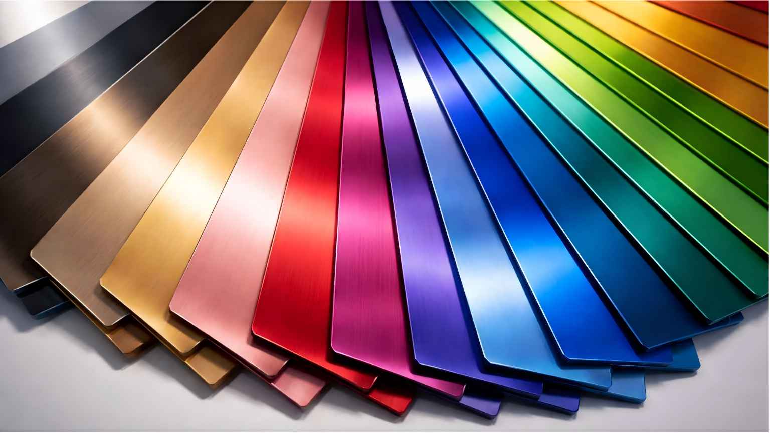
The chamfer is finished before the coating goes on, and the coating grows out of the aluminium rather than sitting on top of it, so it changes the dimensions you machined. Type II sulfuric anodising runs 5–25 µm and suits cosmetic and general parts; Type III hard coat runs 25–75 µm or more and is chosen for wear surfaces. The growth splits across the surface, so a bore that has to fit a bearing at 20.000 mm after a 10 µm Type II coating shrinks by about 5 µm per side, or 10 µm on the diameter, which means machining it to roughly 20.010 mm beforehand.
| Coating | Typical thickness | What it gives | Where it fits |
|---|---|---|---|
| Type II (sulfuric) | 5–25 µm | Corrosion protection, dyeability, moderate wear | Cosmetic and general parts |
| Type III (hard coat) | 25–75 µm or more | High wear resistance and hardness | Wear surfaces, tooling, high-use parts |
The arithmetic matters on a panel as much as it does on a bore. A chamfer that keeps its gloss after coating is one where the chamfer geometry was specified with the coating thickness already accounted for, not one where the coating was treated as a colour step at the end. Both the thickness bands and the tolerance arithmetic come from the shop’s notes on anodising coating, tolerances and colour for CNC parts.
What to Ask For With an Anodised Order
An anodised panel is difficult to rework: stripping and re-anodising changes the dimensions a second time, and a polished edge that has already been coated cannot be polished again without losing the coating. The records are therefore worth more than usual, and every one of them is concrete: the material certificate naming the alloy and heat, a first-article inspection report covering the chamfer width and the critical dimensions, a coating thickness measurement from the anodising line, a colour and gloss master sample agreed before the batch runs, and the process record for the anodising tank. Where a supplier has no certificate to hand, the honest answer is that it is available on request.
Two boundary conditions are worth writing into the drawing before release. A sharp edge will always draw a heavier deposit than a flat face and is the first place to chip, so edges that will be handled should be broken deliberately rather than left as machined. And the finish behaves differently on different alloys: racking and contact marks, coating allowance and colour consistency are all geometry-and-alloy decisions, as the shop’s guide to designing parts for plating and anodising sets out.
FAQ
Why does the width of a glossy chamfer vary?
Because the chamfer depth varies: width is depth divided by the tangent of the chamfer angle, so any uneven clamping pressure, fixture deflection or drifting depth datum shows up directly as a varying bright band. The correction is fixture and process control, not extra polishing.
Can an anodised edge be polished to a mirror finish?
The chamfer has to be polished before it is anodised. Anodising is a conversion coating that grows out of the aluminium, so polishing after coating removes the coating itself. Specify the chamfer geometry, the surface roughness target and the chamfer width on the drawing, and let the finish follow the machined form.
How much does anodising change the dimensions?
Type II sulfuric anodising adds 5–25 µm and Type III hard coat adds 25–75 µm or more, splitting across the surface. As a working example, a 10 µm coating shrinks a bore by about 5 µm per side, or 10 µm on the diameter, so a 20.000 mm fit requires machining to about 20.010 mm.
Which aluminium alloy anodises most consistently?
6061 and 6063 anodise consistently and are the usual choice for cosmetic work. Alloys with heavier alloying additions tend to produce a darker or streaked appearance, so colour consistency across a project is an alloy decision as much as an anodising one.
What quality records should I ask for on an anodised panel order?
The material certificate naming the alloy and heat, a first-article inspection report covering the chamfer width and critical dimensions, a coating thickness measurement, an agreed colour and gloss master sample, and the anodising process record. Ask before the batch runs; not every shop keeps these for every job.
Latest Post
Vacuum Casting VS Injection Molding: How to Choose the Right Manufacturing Process from Prototype to Production
History of CNC Machining: The Origins and Development of Computer Numerical Control
The Ultimate Guide to Injection Molding: Process, Types, Advantages & Applications
How to Choose the Right 3D Printing Process: An Analysis of Pros and Cons
What is CNC Machining?A Complete Guide to Processes,Advantages,and Applications
Sheet Metal Enclosure Design: Corners, Sealing and Service Access
K Factor Sheet Metal Bending: Why the Same Model Gives Two Different Blanks
Custom Metal Fabricated Assemblies: Buying the Finished Item, Not the Parts
Laser Cut Prototypes: Flat Part Design and What the Cut Edge Gives You