

A heat sink is a geometry problem before it is a thermal one. The fins exist to create surface area, the channels exist to direct airflow, and the base exists to carry heat from the component into that geometry. Milling produces the geometry: high fin density, precise channel walls, thin structural ribs, and microchannel patterns that casting and extrusion cannot hold. The discipline of milling heat sinks is matching the thermal goal to what the tool can actually cut, because a fin pattern that looks right on the model and breaks in the machine is not a design, it is a scrap part. This article explains how thermal goals become machining geometry, what fin and channel design can realistically do, and how to verify that the part you receive performs the way the model promised.
Start From the Thermal Goal, Not From a Picture
A heat sink exists to meet a number: a maximum junction temperature at a known heat load, inside a defined air flow or liquid flow budget. Everything after that, the fin dimensions, the channel layout, the base thickness, follows from that goal. Design that starts from a picture of a finny block produces a part that looks right and underperforms. Design that starts from the number produces geometry with a purpose.
The engineering sequence is straightforward. Define the heat load in watts and the allowed temperature rise. Determine the required surface area from the available air flow and the expected heat transfer coefficient. Translate that surface area into fin geometry, and translate fin geometry into a machining plan. Each translation narrows the options, and the machinable envelope constrains all of them. If the required fin density is beyond what the tooling can hold, the answer is more air flow, a bigger sink, or a different cooling approach, not a thinner fin that deflects in the cut.
Fin Geometry: What Milling Actually Holds
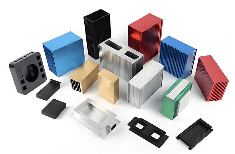
Milling fins from solid material gives control that extruded or cast sinks do not: tight pitch, varied height, and pockets that improve flow around the base. But the geometry is limited by three machining realities. First, fin height relative to pitch sets the tool reach: a tall, narrow fin needs a long, slender tool, and a long tool deflects. Second, thin fins at the free edge are where chatter appears, leaving tool marks that change the effective geometry and add turbulence. Third, the base has to be thick enough to spread heat and rigid enough to hold the fin roots without vibration.
The practical approach is to specify the thermal requirement first, then let the fin geometry land inside the machineable envelope. If the target density forces fins thinner than the tooling can hold cleanly, the design should change the airflow, the material, or the interface rather than push the process past its limit. A machinist who tells you the fin pattern is over the edge is giving you engineering value; a quote that accepts it without comment is planning to struggle with your part.
Air Flow: Spacing Is a Fluid Problem
Surface area is only useful if air reaches it. Fin spacing sets a balance: too tight and boundary layers merge and stall, too wide and the area you paid for disappears. The useful range depends on whether the enclosure is fan-forced or natural convection. A fan gives static pressure to push through denser fins; natural convection needs wider channels and vertical orientation so the heated air can rise. A milled sink can vary spacing across the part, denser over the hot spot and wider where flow is weak, which is exactly the flexibility that makes machining worth it on an enclosed device.
Base Thickness and the Thermal Interface
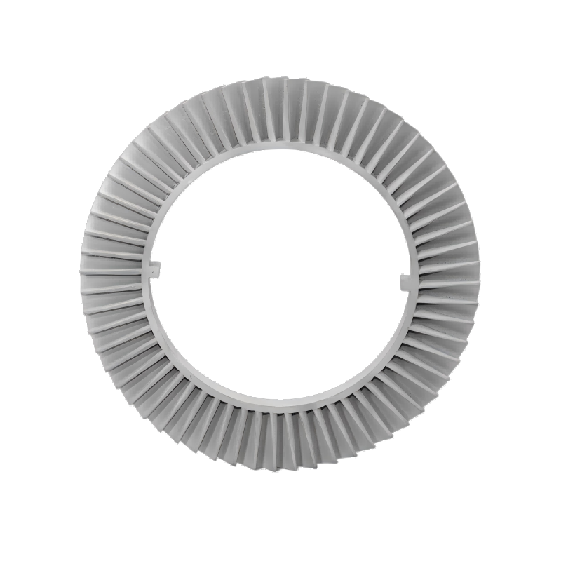
The base is where a heat sink quietly fails. A thin base under a concentrated source cannot spread heat to the outer fins; the center fins saturate and the outer fins stay cold. For a single hot chip or a concentrated power rail, the base must be thick or fitted with a spreader behavior, so lateral conduction reaches the fin roots. The interface matters equally: a flat, cleanly machined base reduces the layer of thermal interface material the joint needs, and integral mounting bosses hold the component at a consistent height so the interface stays even.
State whether tolerances apply before or after finishing. An anodized base adds a thin oxide layer that rarely matters for fit but changes the emissivity slightly; a plated or coated base adds measurable thickness. A close-tolerance mounting boss on a coated sink can land out of spec if the coating is not accounted for.
Microchannels and Liquid Cooling
When air cannot carry the heat, liquid does, and microchannel plates are where milling earns its reputation. A microchannel cold plate is a thin part with closely spaced, high-aspect channels that increase surface area in a liquid flow. The machining demands are severe: channel depth has to be consistent, because a channel that varies in depth changes the flow distribution; the base has to stay thin and flat so the plate seats against the heat source; and the walls have to stand without collapsing during the cut. Microchannel plates also need clean, burr-free entry and exit so the fluid path is not disturbed by machining debris.
The inspection on a microchannel plate is dimensional: channel width, depth, and pitch at multiple points, plus flatness of the sealing face. A first article report that only checks overall thickness misses the channels, which are the part. Ask how the channels are measured, because that tells you whether the supplier can actually verify what they promised.
Verification: Thermal Test Beats a Fin Table
The final measure of a heat sink is not the drawing, it is the system temperature. A thermal test on the actual enclosure, with the real component and load, at the real ambient, tells you whether the geometry did its job. Compare the hot-spot temperature with the current sink and the proposed sink under the same conditions. A few degrees at the junction is worth more than any number of fins on paper.
Working With a Machining Partner
- Send the thermal inputs: source wattage, allowed temperature rise, airflow or liquid flow, and enclosure constraints.
- Send the mechanical interfaces: mounting holes, boss heights, standoffs, gasket lands, and cutouts.
- Confirm the fin, channel, and base geometry is within the machinable envelope before quoting.
- Specify the finish and whether tolerances apply before or after it.
- Agree on a system-level thermal validation for the first article.
Bottom Line
Milling heat sinks works when the thermal goal drives the geometry and the geometry respects the machining limits. Set the heat load and the allowed temperature first, design fins and channels to the airflow and the tooling envelope, keep the base thick enough to spread heat, and verify the result with a thermal test. A milled sink is competing against the temperature at the component, not against other drawings. Get the parts to that number, and the geometry choices were right.
Choosing the Fin Geometry by Airflow, Not by Habit
Fin geometry is a set of choices with a fluid boundary. The natural starting point is the airflow: fan-forced enclosures can push air through denser fins, while natural convection needs wider spacing and vertical features. The milled sink has the freedom to vary spacing across one part, denser over the hot source and wider where the flow is weak, which is exactly the flexibility that makes machining the right process for an enclosed product. The design question is always the same: add surface area only as long as the air still crosses it, then stop.
The Base, the Bosses, and the Interface
The base is where a heat sink silently fails. A thin base under a concentrated source cannot spread heat to the outer fins; the center saturates and the outer fins stay cold. For a single hot chip or a concentrated power rail, the base must be thick enough to spread laterally before the fins take over. The interface matters equally: a flat, cleanly machined base reduces the thermal interface layer needed, and integral mounting bosses hold the component at a consistent height so the interface stays even. These are the details a catalog extrusion cannot control, and where machining earns its cost.
How to Read a Heat Sink Quote
A heat sink quote should answer three questions before the price: which geometry is being machined, what surface is being held, and how the part is verified. Compare the fin pitch, the channel depth, and the base thickness against the thermal requirement, not against a generic drawing. Confirm the finish step and whether it changes the fitting faces. And confirm the inspection: a thermal part is measured on the features that carry the heat, not on the overall envelope.
Anodizing and the Surface Story
Anodizing a heat sink is a common finish because it improves corrosion resistance and gives a consistent appearance, and it adds a thin layer that slightly increases surface emissivity. It does not improve conduction; the aluminum still carries the heat. The finishing decision is about the surface and the fit, not about thermal performance. State whether tolerances apply before or after anodizing, and confirm the anodize type the design assumes for emissivity, if emissivity is being claimed.
The Warm Run: Thermal Validation That Means Something
The only test that tells the truth about a heat sink is a system-level warm run: the real component, the real load, the real ambient, the enclosure closed. Compare the junction temperature with the current sink and the proposed sink, long enough for the system to reach steady state. A short burst test can look good and miss the steady-state problem. A sink that passes the full warm run at the target temperature is the one that earns its place in the product.