

At a hypothetical 20 W heat load, an added interface resistance of 0.2 K/W contributes 4 K of temperature rise. That simple illustration explains why a fin drawing alone cannot define a successful cooler. CNC machined heat sinks need manufacturable fins, a controlled contact interface, and a thermal test that represents the installed system.
Fin geometry manufacturability
Specify CNC machined heat sinks by the fin geometry, tool access, base contact requirements, material, finish, and operating conditions. Review narrow channels and thin fins for machining and handling risks. Validate the finished assembly with its actual interface material and airflow rather than treating machined dimensions or extra surface area as proof of cooling performance.
Provide channel width, fin height, fin thickness, root geometry, and any cross-cut features together. A channel that admits the cutting edge may still restrict the tool shank or require a long, flexible assembly. Identify whether a larger root radius or revised fin spacing is acceptable before the supplier develops the process.
Boyd’s heat-sink fabrication guide compares several fin and manufacturing routes. Use that range to question whether every fin needs to be milled from a solid blank. The milling review should identify which geometric details drive access, finishing, and inspection work.
Base flatness for TIM
Define the base surface that contacts the heat source or spreader, the installed support, and the permitted form. A low roughness value does not establish flatness, and flatness alone does not establish the interface’s thermal resistance. Keep surface texture, form, and assembly loading as separate requirements.
Texas Instruments’ thermal-management application report discusses interface material, mounting pressure, thickness, and surface flatness in its device-mounting context. The relevant lesson is to review the whole contact arrangement, not to copy one package’s mounting instructions into an unrelated assembly.
Use the drawing’s selected geometric convention. ASME Y14.5 provides the language for form and datum-related requirements. Identify the functional contact extent and inspection state. A base inspected while forcibly clamped flat may not represent the condition before installation, while a specified assembly restraint needs its own controlled interpretation.
Anodizing and thermal trade-offs
Specify anodizing or another finish by the intended function and the surfaces it may affect. Color, corrosion protection, electrical behavior, and the thermal contact path are different considerations. Do not assume that a black appearance establishes a better installed temperature without evaluating the actual cooling conditions.
Mark the TIM contact region, masked surfaces, mounting holes, and any interface that depends on electrical contact. A finish changes the delivered surface condition and may require the component dimensions and assembly plan to be reviewed. Confirm whether the accepted thermal prototype will include the same finish as the production part.
AMD’s TIM guidance discusses factors affecting the use and performance of interface materials for its devices. Apply the actual device and TIM supplier’s requirements to this assembly. An interface choice cannot be evaluated reliably from the heat sink’s material name and coating color alone.
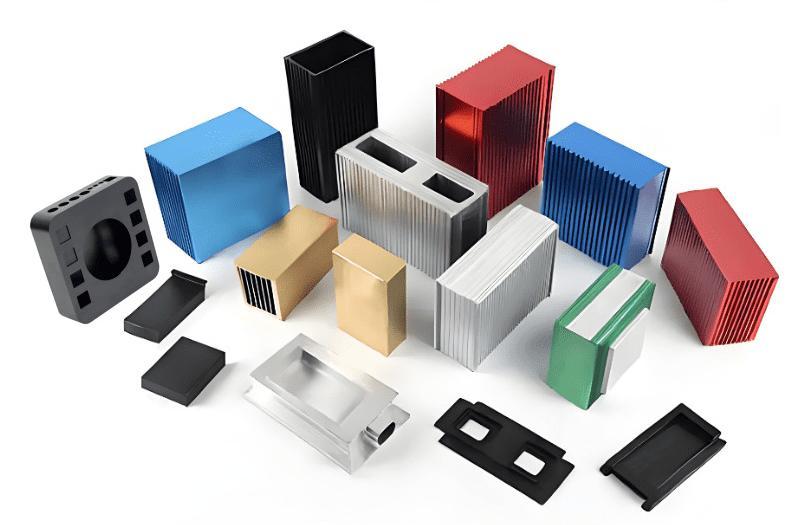
Table: design checks
Use one review table to connect the drawing with the installed test. The manufacturer needs to know which dimensions establish acceptance, while the thermal engineer needs the boundary conditions used to evaluate cooling. Neither group should infer the other’s requirements from a generic heat-sink description.
Complete the checks before release and identify the owner of every open item. Keep the mechanical inspection plan distinct from the system thermal verification.
| Area | Drawing or process check | System check | Evidence |
|---|---|---|---|
| Fins and channels | Tool access, root geometry, burr limits, handling | Installed airflow and orientation | DFM response and representative thermal trial |
| Base | Contact extent, form, texture, inspection state | TIM and mounting arrangement | Surface inspection and assembly record |
| Finish | Specified treatment and masking | Contact and exposure requirements | Finished sample and relevant test |
| Mounting | Hole pattern and mating dimensions | Load distribution and device restrictions | Controlled assembly method |
Do not add an unsupported thermal rating to the manufacturing drawing. State the required test conditions and acceptance result separately where the project needs thermal qualification.
Prototype to production
Use prototypes to resolve a named uncertainty: geometry, mounting access, interface contact, airflow, or the thermal result. A machined prototype may reproduce custom mounting details while leaving the production fin route undecided. Record which features and material conditions must remain representative.
Wakefield Thermal’s skived-fin information describes another way to produce fins. Comparing skived and CNC fins requires the actual geometry, material, quantity, and downstream work; one process label does not establish a universal cost or performance advantage.
For the aluminum material review, identify the alloy, condition, starting form, and required finish. If production changes from billet machining to a profile or another fin route, check the base, interface, mounting, and thermal assumptions again. A successful prototype test is evidence for its tested configuration, not automatic approval of a different production construction.
FAQ
These questions address specification details that should be settled before sample approval.
Does increasing fin count always improve cooling?
No. The result depends on geometry, airflow, orientation, and the rest of the thermal path. More surface area can also create narrower passages and different manufacturing constraints. Evaluate the proposed design under the installed conditions rather than ranking heat sinks by fin count alone. Keep the tested configuration traceable to the drawing and finish.
Can a thick TIM compensate for any base-flatness issue?
No. The selected TIM has its own usable gap, compression, mounting, and thermal requirements. Review the actual base geometry and installed contact with the device and TIM supplier’s guidance. A thicker layer may change the thermal path and should not become an informal repair for an undefined surface requirement.
Does a machined sample validate an extruded or skived production version?
It can inform the design, but changes in construction, contact geometry, material state, and finish require review. Identify what remains equivalent and what must be checked again. Preserve the mounting and thermal test conditions when comparing versions so that a result from one configuration is not extended to a different part without evidence.
Related process selection notes
Choose the process around the complete part and expected release quantity. Machining can be useful for custom pockets, mounting faces, or a low-volume geometry that does not justify another tooling route. A suitable profile with CNC finishing can be a candidate when the fin section is repeatable and only local features vary.
Review the full CNC machining scope instead of comparing only fin-cutting time. Include starting material, workholding, secondary operations, deburring between fins, surface treatment, and inspection. Protect narrow or thin fins during handling so that the delivered geometry matches the approved design.
Keep any thermal estimate tied to its assumptions. In the opening illustration, multiplying 20 W by 0.2 K/W gives 4 K for that hypothetical interface contribution. It does not predict the device junction temperature or establish an accepted thermal resistance for a 6CProto part. The remaining heat path and operating conditions still need evaluation.
Internal links and next steps
Send the controlled CAD and drawing with the heat-source contact area, proposed TIM, mounting arrangement, airflow direction, orientation, material, finish, and required quantity. Identify which thermal requirements are supplied design targets and which tests must be performed or documented.
For a consumer-electronics cooling project, include the installed enclosure constraints that affect access or airflow. Ask the manufacturing response to identify fin limitations, base inspection, masking, and any suggested geometry changes. Approve changes against both the mechanical and thermal requirements.
Request a 6CProto quote and DFM review with the fin drawing and thermal-interface requirements. Confirm the manufactured condition and the system validation plan before treating the prototype as production-ready.