

Compare two hypothetical heat-management prototypes with similar fin envelopes. One uses a heavier copper spreader; the other has an aluminum body with a better-controlled mounting interface. If their measured temperatures differ, the material names alone cannot explain why. Reconstruct the interface, finish, assembly, and test conditions before deciding what the next machined revision should change.
Flatness for TIM
Specify CNC heat sinks for electronics through the heat path, interface flatness and texture, actual TIM, mounting, material, fins, finish, and operating conditions. Inspect the required final surfaces and validate the assembled thermal design. A conductivity value or attractive fin array cannot establish contact performance, device loading, or cooling under an untested installation condition.
Start the hypothetical review by identifying the heat-source footprint and the surfaces intended to meet. Record the base and package geometry, support, fastener or clip arrangement, TIM identity, and assembly state. Distinguish a free-part flatness measurement from the shape under installed loading.
ASME’s Y14.5 overview describes the language of geometric requirements. Use the applicable drawing convention to specify form and relationships; do not substitute a roughness number for flatness or a nominal surface for a complete mounting requirement.
Nordson EFD’s compound-selection guide distinguishes conductivity, resistance, and bond-line effects. Choose the actual material and application route for the interface. More compound or a higher advertised conductivity should not replace a review of contact geometry and installed thickness.
Fin and spreader manufacturability
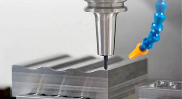
The second review step is to reconstruct the manufacturing route. Identify which surfaces were machined, the stock form, local finishing, residual burrs, and the inspection state. Check whether thin bases or clamping can influence the released contact surface. Obtain evidence for the specified geometry rather than assuming the setup held it flat throughout.
Review fin channels with the cutter, holder, workholding, and required edge condition. Long narrow channels can complicate access and handling. Confirm root radii, fragile edges, mounting holes, and any secondary cuts. A visually similar fin envelope can come from different constructions with different interfaces.
Boyd’s heat-sink fabrication guide compares manufacturing and fin options. Use it to consider whether the selected design needs full machining, a prepared extrusion, or another approved construction. A change in fabrication route should trigger review of material, geometry, contacts, and the evidence transferred from the prototype.
Record which feature limits production or inspection and whether changing it affects the thermal objective. A larger channel can improve machining access while changing airflow and surface area. Evaluate the revised assembly rather than optimizing the machining and thermal models in isolation.
Table: Al vs Cu
The third step compares materials and geometry on a consistent basis. Use actual grades and conditions for numerical properties. This qualitative table organizes the decision without assigning a universal conductivity, price, or allowable temperature to every aluminum or copper part.
| Question | Aluminum candidate | Copper candidate | Evidence needed |
|---|---|---|---|
| How is heat spread? | Assess selected alloy and geometry | Assess selected grade and geometry | Relevant property data and thermal model |
| What mass can the assembly carry? | Compare completed part mass and support | Account for the denser material and mounting | Actual assembly loading review |
| How is the part made? | Stock form, fins, pockets and finishing | Tooling, stock, joining and finishing | Complete proposed route |
| What controls the interface? | Flatness, texture, finish and TIM | Flatness, texture, finish and TIM | Final-condition measurements and trial |
Do not compare a thick copper block and a thin aluminum plate as if material were the only variable. Identify the controlled variables and the design objective. The best-supported choice is the one whose complete configuration meets the required temperature, mass, space, and acceptance constraints.
Finish impact on thermal
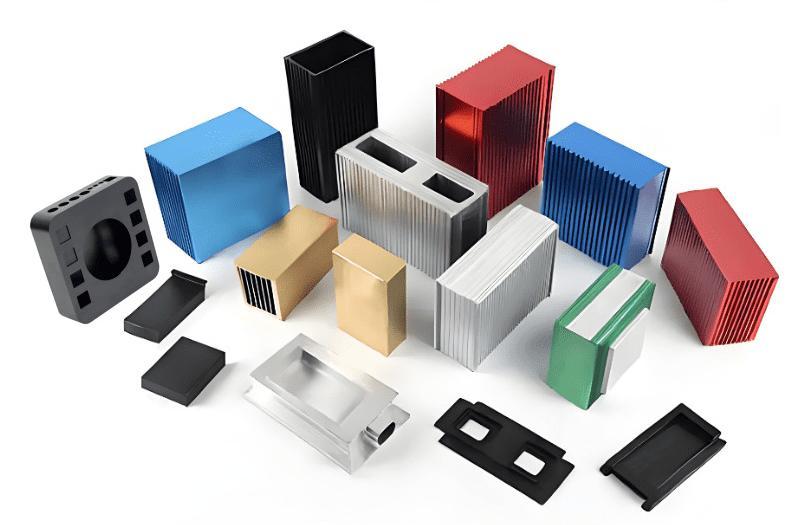
The fourth step separates the finish on exposed surfaces from the mounting interface. Specify masking, contact state, electrical requirements where relevant, and final inspection. A finish may serve appearance or protection while introducing another consideration at the heat-transfer contact.
Arma Elektronik’s thermal-finishing guidance distinguishes convection, radiation, contact conditions, and measurement. Avoid inferring a fixed improvement from black color. If infrared imaging is used, account for the different surface emissivity and verify the measurement method before comparing apparent temperatures.
Keep the prototype finish representative of the proposed delivery. If the trial used an uncoated interface but production includes a coating there, reassess the contact and relevant evidence. Mark permitted finish boundaries on the drawing so they are preserved through processing and handling.
FAQ
These questions address specification details that should be settled before sample approval.
Does copper guarantee the lowest device temperature?
No. Material conductivity is one part of the thermal path. Geometry, heat spreading, interfaces, mounting, airflow, and enclosure conditions affect the result. Compare the actual designs under the same relevant conditions and include mass and manufacturing consequences.
Is roughness the same requirement as flatness?
No. They describe different surface characteristics. Define each requirement needed by the interface and use an appropriate inspection method. A low roughness value cannot establish that the whole mounting surface has the required form.
Related process selection notes
Complete the hypothetical review by aligning the assembly and test. AMD’s TIM guidance identifies application, spreading, stability, electrical behavior, and pressure considerations for its devices. Follow the actual package and TIM supplier requirements; do not transfer mounting limits between unrelated devices.
Record power, ambient and inlet conditions, airflow, orientation, enclosure, mounting, TIM application, sensor locations, measurement method, and the criterion for reaching the reported state. Change one relevant variable at a time where feasible, or explain the comparison’s limitations. A different result under a different fan or load is not a material-only experiment.
Retain part revisions and assembly records with the findings. Identify whether the next action is improved contact control, a different spreading geometry, revised fins, another material, or further measurement. Close the limiting evidence gap before selecting a visually convincing replacement.
Internal links and next steps
Send the model, drawing, quantity, heat-source layout, target conditions, material candidates, TIM, mounting requirements, finish map, and acceptance plan. Review the application through consumer electronics and the route through CNC machining. Compare aluminum and copper against the complete thermal and mechanical scope.
Request a thermal-part quote with contact geometry and installed test conditions defined. Confirm the proposed material, route, and final-surface inspection before ordering.
FAQ
These questions address specification details that should be settled before sample approval.
Can extra TIM fill any mounting gap?
No. Select the actual material for the required gap, pressure, application, and thermal performance. Check device loading limits and installed geometry. Do not use added material as an unreviewed repair for an undefined surface or mounting problem.
Does black anodizing always improve the installed result?
No. Separate radiation effects on exposed surfaces from effects at the contact interface, and account for airflow and geometry. Compare representative finished assemblies. Color alone and an uncorrected thermal-camera image do not establish a temperature benefit.