

Most heat sinks sold with straight fins are extruded, and most heat sinks with demanding geometry are machined. The choice between them comes down to three things: the fin ratio the design needs, whether a die can be justified, and how much of the part has to be produced accurately rather than formed. Skiving sits between them for dense fin fields. This comparison sets out the limits of each route, the tooling implications and where the volume breakpoints fall.
Extrusion or machining: which route fits?
Extrusion for straight fins at volume, machining otherwise.
An extruded profile is economical where the cross-section is constant and the volume justifies a die, while machining suits complex geometry, prototypes and parts with demanding interfaces.
The structural difference is what makes extrusion attractive: a profile is pushed through a die, so every unit has the same cross-section and the cost per part falls to the price of the material plus the cutting operation. That makes it the lowest-cost route for a heat sink with straight fins and a constant profile, provided the volume is large enough to recover the die.
Machining works from stock and cuts the geometry, which means no die and complete freedom in the base features. Pin fins, tapered fins, curved outlines, pockets for components and complex mounting geometry are all straightforward, and the design can change with a new program. The cost per part is higher, because the machine removes material rather than forming it.
The decision therefore starts with the geometry and ends with the volume. Where the profile can be constant and the quantity is high, extrusion wins on cost. Where the base is complex, the quantity is low, or the design is still moving, machining is usually the practical route.
What limits the fin ratio in each process?
The die in extrusion, the tool in machining.
Extrusion is limited by how thin a fin the die can form and how well the metal flows through it, while machining is limited by tool rigidity and the forces involved in cutting between fins.
Fin ratio describes how tall a fin is relative to its thickness or spacing, and it is the parameter that determines both thermal performance and manufacturability. In extrusion, a high fin ratio means the die has narrow slots through which the aluminium has to flow, and the fins have to survive being pushed out of the die and cooled without collapsing. That limits how fine the fin field can be, and the limit depends on the alloy and on the die design.
Machining has a different constraint. Each fin is cut by a tool that has to pass between the fins without deflecting, and the depth to which it can reach depends on its diameter and rigidity. Producing a dense, tall fin field by milling is therefore slow and prone to poor finish at the base of the channels, and the practical limit is lower than the thermal analysis might prefer.
Skiving circumvents both limits by forming the fins from the base material with a peeling action, which allows thin, tall fins that neither extrusion nor milling can match. Where the thermal requirement demands a high fin ratio, skiving is often the only route that delivers it, and its own constraint is that the fins must run in a direction the tool can follow.
How do tooling and minimum quantities compare?
One needs a die; the other needs only a program.
Extrusion requires a die whose cost has to be recovered across the run, while machining requires programming and fixturing that are far cheaper but are reflected in a higher cost per part.
The die is the defining cost of extrusion. It is a bespoke tool that only pays for itself over a quantity, and it also fixes the design: a change to the profile requires a new die or a modification to the existing one. That makes extrusion unsuitable for development work, where the fin geometry is still being optimised, but very efficient for a product that has settled into a stable profile.
Machining has no such barrier. A program and a fixture are relatively inexpensive, and the design can be revised between runs without scrapping a tool. The trade is the per-part cost, which stays high because the material is removed rather than formed. For a low volume, that is the correct trade; the machined part costs more per unit but nothing is invested in a die.
The breakpoint depends on the part size and the die cost, but the pattern is consistent: a simple profile at moderate volume is cheaper extruded, while a complex geometry or a small quantity is cheaper machined. Asking for both routes to be quoted at the anticipated quantity makes the crossover visible.
| Factor | Extrusion | Machining |
|---|---|---|
| Tooling | Bespoke die | Program and fixture |
| Cost per part | Low at volume | Higher; material is removed |
| Fin ratio | Limited by the die | Limited by tool rigidity |
| Geometry freedom | Constant cross-section only | Full, including pin fins |
| Design change | Requires a new or modified die | Requires a new program |
| Typical use | Standard profiles in volume | Prototypes, complex bases, low volume |
How do lead time and tolerance compare?
Machining is quicker to first part; extrusion to volume.
A machined heat sink can be produced without a die, while an extruded one waits for the die to be made and then for the profile to be cut and finished.
The die dominates the lead time for a new extruded design. Designing, making and proving a die takes time before any profile exists, and if the first profile reveals a thermal problem the die has to be modified. That sequence is why extrusion belongs to a settled design, and why programs often start with a machined or skived part while the profile is being proven.
Tolerance follows the process. An extruded profile holds a looser tolerance on the fin geometry and on the overall dimensions, because the material moves as it is pushed and cools. Machining holds tighter tolerances on the base, which matters where the sink has to sit flat against a component or match a mounting pattern. That is one reason a hybrid design is common: an extruded body for the fins with a machined base or insert for the interface.
Surface finish differs as well. Extruded profiles carry die lines that are visible on the fin faces, and the base is normally machined or faced before use. Machined heat sinks have a consistent finish across the part, which matters where the contact face is part of the same operation as the fins.
When does skiving beat both?
When the fins have to be very fine.
Skiving forms thin, tall fins by peeling them from the base material, which achieves fin ratios that neither extrusion nor milling can reach.
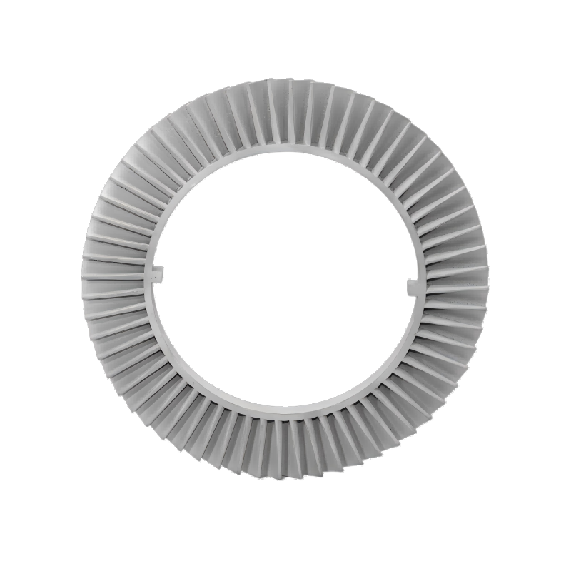
The process works by running a tool along the surface and lifting a continuous fin, in the way a plane raises a shaving. Because the fin is formed rather than cut free or pushed through a die, it can be made thin relative to its height, and it remains continuous with the base, which removes an interface resistance. That combination is why skived heat sinks appear in compact, high-dissipation products where the fin field has to be dense.
Its constraints are geometric. The fins have to run in a direction the tool can follow, which usually means straight, parallel fins rather than a pin pattern. The base can be shaped afterwards by machining, so a skived sink can carry mounting features and pockets, but the fin field itself is limited to what the process produces.
Cost sits between extrusion and machining. Skiving requires no die in the extrusion sense, but the equipment and the tooling are specialised, and the process is not suited to very small quantities. It becomes economical where the fin density is a requirement and the volume is meaningful, and it is often combined with machining for the base.
How does a program move from prototype to production?
By proving the geometry before committing to a die.
A common sequence is to machine or skive the first units, validate the thermal performance, then move to an extruded profile once the fin geometry is stable.
The advantage of that sequence is that the thermal design is proven on a part that can be changed quickly. Machined and skived heat sinks can be revised between iterations without tooling cost, which makes them the right choice while the fin geometry, base thickness and interface are still being optimised. Once the design performs as required, the profile can be frozen and a die made against it.
The handover then has to preserve the thermal behaviour rather than just the outline. An extruded profile will not reproduce the fin ratio of a skived part exactly, so the transition may require a larger or differently arranged fin field to achieve the same result. The measured performance of the prototype becomes the specification for the extruded version, and the comparison is a thermal one rather than a dimensional one.
Where the volume never justifies a die, the machined or skived part remains the production answer, and the design should be optimised for that route from the start. The extrusion route and its design implications are described on the custom extrusion page and in the existing 6CProto article on extrusion for heat sinks and LED enclosures.
Choosing between the routes
The decision follows the geometry first and the volume second. If the fin field can be a constant profile and the quantity justifies a die, extrusion is the economical route. If the base is complex, the fin ratio is demanding, or the design is still changing, machining or skiving is the practical answer, and the higher cost per part is the price of that flexibility.
Two questions resolve most cases. Does the design need a fin ratio that a die cannot produce? If so, skiving or machining is required regardless of volume. Is the quantity large enough to recover a die? If not, machining remains the answer even for a simple profile. Where the two answers conflict, the usual resolution is a hybrid, with an extruded body and a machined interface. 6CProto reviews thermal components for manufacturability before production and returns a DFM report with the quote, and the interface tolerances are set out on 6CProto’s standards and tolerances page.
FAQ
What are the two main types of heat sink?
By manufacturing route, the two common types are extruded heat sinks, where the fins are formed as a constant profile, and machined or skived heat sinks, where the fins are cut or peeled from solid material. Extruded types are economical at volume with straight fins; machined and skived types allow complex bases and finer fin fields. Many production designs combine an extruded fin body with a machined interface.
What is an extruded heat sink?
It is a heat sink whose fin profile is pushed through a die as a continuous length of aluminium, which is then cut to the required size and usually machined at the base. Because the profile is constant and the die does the shaping, the cost per part is low once the die is amortised. The trade is that the design is fixed by the die and the fin ratio is limited by what the die can form.
What are the disadvantages of aluminium extrusion for heat sinks?
A die is required, which makes the route unsuitable for low volumes or for a design that is still changing. The fin ratio is limited by how finely the die can form and how the metal flows, so very dense fin fields are out of reach. Tolerances are looser than machining, and the surfaces carry visible die lines, so the base is usually machined before use rather than used as extruded.
When should a heat sink be skived instead?
When the fin ratio needs to be higher than extrusion or milling can achieve. Skiving forms fins by peeling them from the base material, which allows them to be thin relative to their height and keeps them continuous with the base. The constraint is that the fins must run in a direction the tool can follow, so pin patterns and complex fin arrangements remain machining work. The standards, materials data and regulatory framework referenced in this article are published by ASTM committee B08, ASTM D3359, ASTM committee D20, ASTM committee E28, ASM International.
If a heat sink design has to be matched to a production route, send the model with the fin ratio, the base features and the quantity you expect. 6CProto runs extrusion, machining and skiving through its partner network, so the routes can be compared from one manufacturing review. Upload the file at the 6CProto quote page or send it to projects@6cproto.com.